T8 Torque Sensor Operation Manual
Interface Inc. ● 7401 East Butherus Drive, Scottsdale, Arizona 85260 USA ● Phone 480.948.5555 ● Fax 480.948.1924
www.interfaceforce.com ● Email: contact@interfaceforce.com ● 800.947.5598
Page 7 of 11
Connections with Clamping Piece:
The indications of the clamping piece manufacturer must be considered. The clamping piece must be able to
transfer the arising torques safely.
Caution: During the assembly inadmissibly large forces may not act on the sensor or the couplings. At
small torques (< 20 N·m) connect the sensor electrically during the assembly and observe the signal,
the measurement signal may not exceed the limit values
Torque Sensors below 20 N·m
Sensors with nominal torques below 20 N·m are very sensitive to overload, therefore these
sensors need to be handled with greatest caution.
1. Connect the sensor electrically during the assembly and observe the measuring signal; the limit values
may not be exceeded in any case.
2. Align the arrangement before the parts are connected firmly.
3. Assemble the sensor at the low torque resistance side first, then at the stationary side (this avoids
impermissibly large torques from acting on the sensor).
4. Counter-hold by hand, so that impermissibly large torques or disturbance variables cannot act on the
torque sensor.
Torque Sensors from 20 N·m and above
The hub must fit corresponding to the connection.
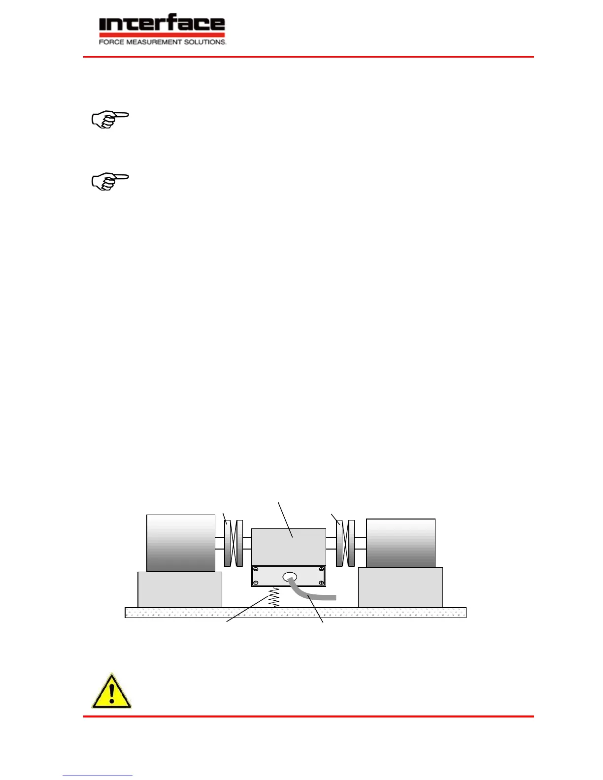
Free-floating Assembly
The sensor is installed between two single-jointed couplings and contributes to the balance of an
inevitable axis offset between the two mechanical connections.
If no couplings are used, very large transverse forces can affect the sensor. In addition, large forces occur on the
bearings, in drive and output, which limit their life span very strongly.
Shafts must be cleaned with solvent (e.g. acetone) before the assembly. No foreign particles may adhere to them.
Shift couplings on shafts (use entire clamping length of the coupling) and align shafts. Absolutely assure that the
data of the couplings (axis offset, angular offset, tension, compression) are not exceeded.
The housing must be protected from twisting e.g. by a flexible connection. The cable connection may not be used
for this.
The cable connection must be placed loosely (form of goose neck), so that it can follow the light
movements of the stator.
Torque sensor
Drive
Single-jointed coupling Single-jointed coupling
Output
Flexible connection for
housing fixation
Cable connection
In this case, with both single-jointed couplings, the torque sensor forms a double-jointed coupling. A
single-jointed coupling can only balance axial and angular misalignments.
In this installation case, double-jointed couplings cannot be used for both sides!
Risk of Breakage!