T8 Torque Sensor Operation Manual
Interface Inc. ● 7401 East Butherus Drive, Scottsdale, Arizona 85260 USA ● Phone 480.948.5555 ● Fax 480.948.1924
www.interfaceforce.com ● Email: contact@interfaceforce.com ● 800.947.5598
Page 6 of 11
Electrical Setup
The electronics integrated in the sensor consists of two parts. The
first part is in the stator and has following tasks:
Stabilization of the supply voltage
Electric supply of the rotor electronics through the rotating transformer
Preparation of the measurement signal from the rotor
Readout of the torque measurement signal to the cable connection
The second part of the electronics is placed in the rotor of the torque sensor and
has following functions:
Supply of the SG full bridge with d.c. voltage Preparation of
the electrical torque measurement signal Transmission of
the measurement signal to the stator
4
Mechanical Assembly
For the assembly of a torque sensor in a shaft line, we always recommend to use couplings which can be misaligned.
Couplings
We recommend multi-disc couplings for our torque sensors. Couplings must be able to balance an axial, radial or
angular offset of the shafts and not allow large forces to act on the sensor. The assembly instructions of the
respective coupling manufacturer must be considered.
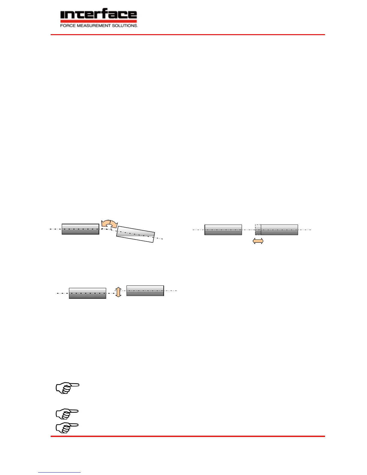
Misalignment Possibilities of Single-Jointed Couplings
Angular Misalignments
Axial Misalignments
Note: Radial misalignments are only possible in the combination of
single-jointed coupling - torque sensor (as adapter) - single-jointed coupling.
Thus, with both single-jointed couplings the torque sensor forms a double-jointed coupling.
Radial Misalignments
Double-Jointed Couplings
Double-jointed couplings are used for the balance of inevitable angular, axial and radial misalignments.
Alignment of the Measurement Arrangement
Precisely alignment of the couplings reduces the reaction forces and increases the durability of the couplings.
Disturbance variables are minimized as well.
Due to the multitude of applications, an alignment of the coupling with a straight edge in two levels, vertical
to each other, is sufficient.
However, in drives with high speed an alignment of the coupling (shaft ends) with a dial gauge or a laser is
recommended.
For further references see coupling manual.
General
Before the assembly, shafts must be cleaned with dissolver (e.g. acetone), no foreign
particles may adhere to them. The hub must fit corresponding to the connection.
During the assembly, the sensor must be supported to protect it from falling down.