Interflex Datensysteme GmbH 10/13
6.8 Adjusting the Reader
Structural conditions may make it necessary to fine-tune or readjust the reader. For this purpose, there is a
hole (10) on the back panel of the housing.
Adjust the reader while the back panel is attached.
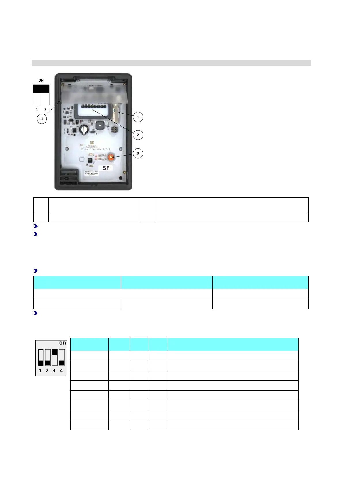
1 Anti-tamper switch 3 Adjusting screw for readjusting the reader
2 Terminal clamps 4 2-pin DIP switch for setting the LEDs
Switch on the power supply and adjust the reader using the adjustment set (order no. 75-99-0004).
Turn the adjusting screw (3) until the field indicator reaches maximum.
Setting the LEDs
You can use the 2-button DIP switch (4) to set the LEDs according to the color of the display. The switch
setting is usually factory preset.
Check the setting of the DIP switches by referring to the table.
Glass, white OFF ON
Glass, black ON ON
Other settings are reserved for additional designs.
6.9 Setting the Hardware Address
Address 1 OFF OFF OFF OFF (not required if connected to a master terminal)
Address 2 ON OFF OFF OFF
Address 3 OFF ON OFF OFF
Address 4 ON ON OFF OFF
Address 5 OFF OFF ON OFF
Address 6 ON OFF ON OFF
Address 7 OFF ON ON OFF
Address 8 ON ON ON OFF
There is a four-way DIP switch on the I/O controller board for setting the hardware address.