Interflex Datensysteme GmbH 9/13
6.7 Electrical Connections
1
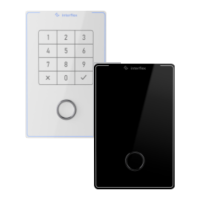
IF-80x terminal 5 Circuit example: Control of an actuator (door opener).
The actuator may only be operated with max. 30 V and
2 A.
2
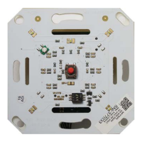
I/O controller board 6 Circuit example: Connection of both inputs.
3
Circuit example: Power Supply 7 Address switch on the I/O controller board
4
Circuit example: RS485 connection. The spur line may
not be longer than max. 100 m.
Bridges:
BR1: When an I/O controller board is used, bridge 1 is always plugged in. If an additional I/O controller
board is used, bridge 1 on the second I/O control board must be removed.
BR2: With bridge 2, the switching contacts of the relay are changed from NO to NC.
BR3: Instead of bridge 3, an anti-tamper switch can be connected.