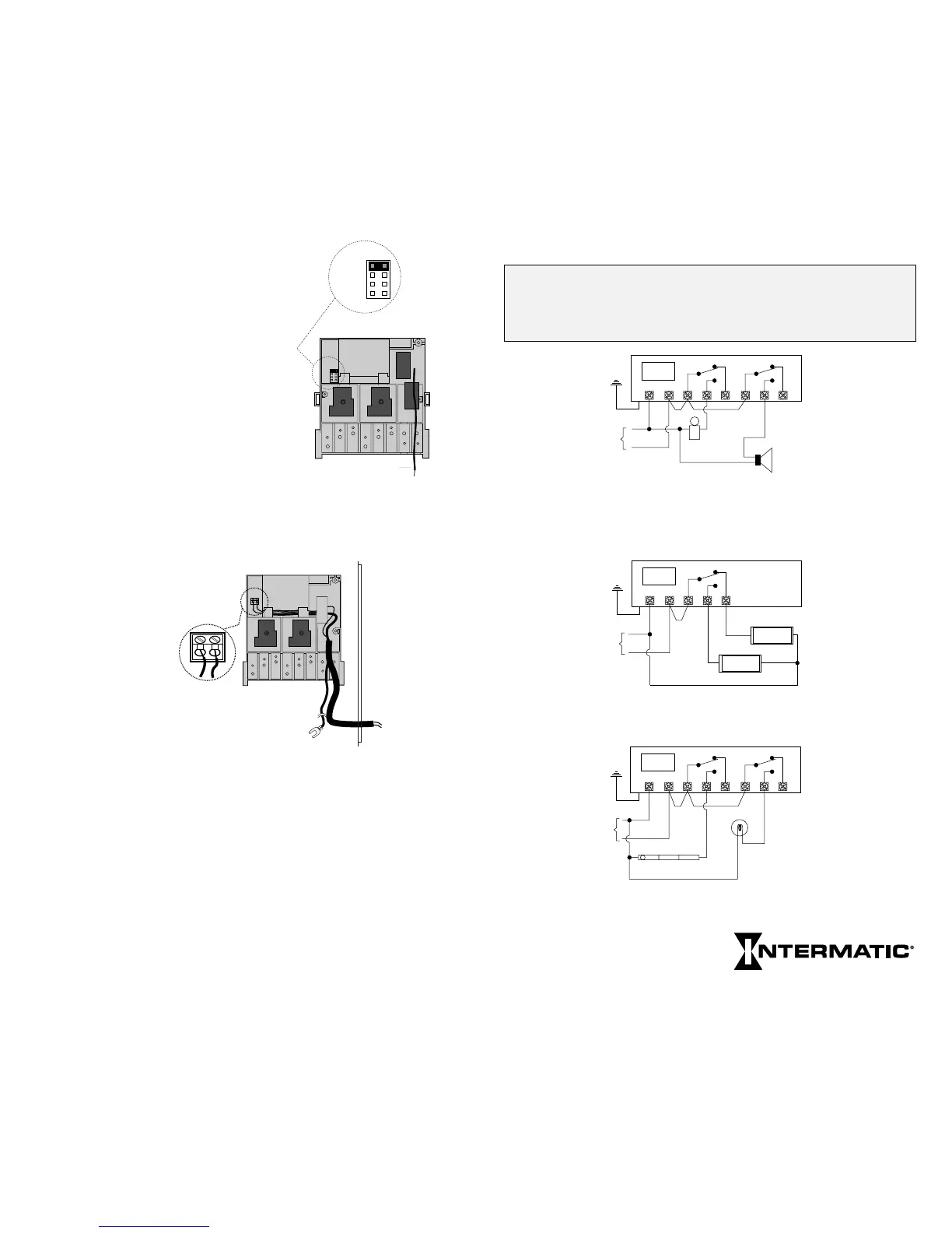
TYPICAL WIRING CONFIGURATIONS (Multi-volt Models)
WARNING: If timer power supply voltage is 208/240/277V,
you must move the input voltage selector jumper on the power
board. See Special Instructions. 24V models do not have this
jumper; connect 24VAC 60 Hz only to 24V timer power terminals.
Circuit #1
Neutral
Hot
Circuit #2
120 VAC
Timer
Power
1 2 3 4 5 6 7 8
ET70215C 2-SPDT 120 Volt Input
Bell and Signal Controls / Pulse and
Interval Switching (Loads and Timer
Powered by Same Source)
Bell
Signal
Equipment
Ground
Neutral
Hot
120 VAC
Timer
Power
1 2 3 4 5
ET70115C SPDT 120 Volt Input
Alternating Sign Control / Fixed Switching
OPEN
CLOSED
Equipment
Ground
Circuit #1
Neutral
Hot
Circuit #2
120 VAC
Timer
Power
1 2 3 4 5 6 7 8
ET70215C 2-SPDT 120 Volt Input
Indoor and Outdoor Lighting / Astro Switching
Circuit #2 Only
Outdoor
Lighting
Indoor Lighting
Equipment
Ground
SPECIAL INSTRUCTIONS
Changing Power Input Voltage–
Multi-Volt Models
ET70115C, ET70115CR,
ET70115CR8, ET70215C,
ET70215CR, ET70215C8
These models can be powered by any
industry standard 50–60Hz AC voltage,
120 to 277V. To change from the
120VAC factory setting, locate the
voltage selector jumper and insert over
the pair marked with the desired voltage
(208, 240, or 277 VAC).
24 Volt Timer Power Wiring–
When Using Bell or Thermostat Wire Only
(Load Voltage Above 24 Volts)
This timer must
be powered by
24 VAC, 60 Hz
only. These is no
supply voltage
adjustment jumper.
If load voltage(s) are
24V or less, and/or if the
timer power wiring insulation
is rated for at least 300V, connect timer power to terminal 1 and
2. If load voltages are greater than 24V and the timer power
wiring insulation is not rated for at least 300V, such as bell or
thermostat wire, feed the timer power wiring through the supplied
insulating tube and connect to the two-place terminal block on
the back of the power module. Once installed, the tubing must
extend beyond the enclosure wall and under the power module so
that the timer power wiring remains isolated from the high voltage
load wiring.
Load Control Wiring With the logic module removed you
have access to the load control relay terminals.
28
120V
208V
240V
277V
120V
208V
240V
277V
Ground
POWER MODULE
(back view)
POWER MODULE
(back view)
Two Place
Terminal Block
Enclosure
Wall
24 Volt Wiring
When Using Bell or
Thermostat Wire
29
Next Generation