30
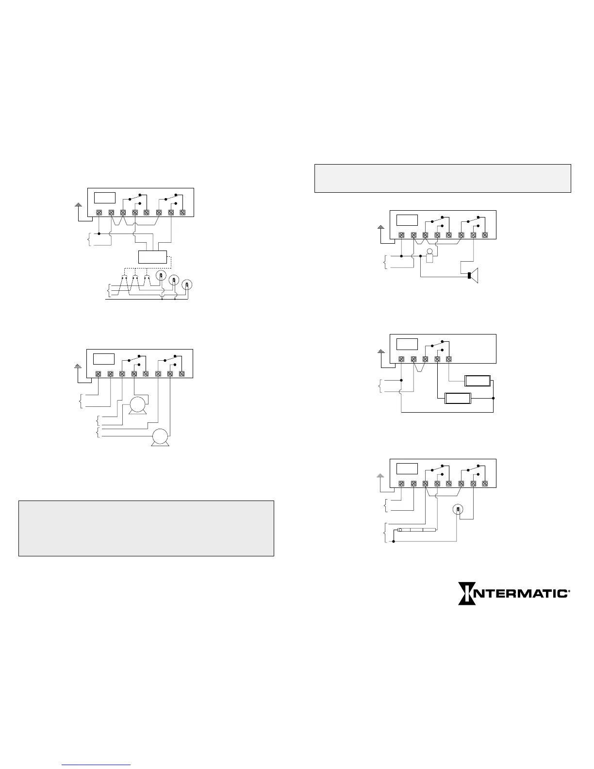
TYPICAL WIRING CONFIGURATIONS (24V Models)
WARNING: Connect 24VAC 60 Hz only to 24V Timer Power
Terminals.
Circuit #1 Circuit #2
24 VAC
Timer
Power
1 2 3 4 5 6 7 8
ET70215CR24 2-SPDT 24 Volt Input
Bell and Signal Controls / Pulse and
Interval Switching (Loads and Timer
Powered by Same 24 Volt Source)
Bell
Signal
Equipment
Ground
24 VAC
Timer
Power
1 2 3 4 5
ET70115CR24 SPDT 24 Volt Input
Alternating Sign Control / Fixed Switching
(Loads and Timer Supplied by Same 24 Volt Source)
OPEN
CLOSED
Equipment
Ground
Circuit #1
Equipment
Ground
Circuit #2
24 VAC
Hot
Neutral
120 VAC
Timer
Power
1 2 3 4 5 6 7 8
ET70215CR24 2-SPDT 24 Volt Input
Indoor and Outdoor Lighting / Astro Switching
Circuit #2 Only (Loads and Timer Each Powered
by Different Sources and Voltages)
Outdoor
Lighting
Indoor Lighting
TYPICAL WIRING CONFIGURATIONS
(Multi-volt Models)
Circuit #1
Neutral
Neutral
Hot
Circuit #2
Latching
Relay
ON C OFF
Outdoor
Lighting
277 VAC
277 VAC
Timer
Power
1 2 3 4 5 6 7 8
ET70215C 2-SPDT 277 Volt Input
Latching Type Lighting Contactor
Astro Pulse Switching
Equipment
Ground
Circuit #1
Line 1
Line 1
Line 1
Line 2
Line 2
Line 2
Circuit #2
240 VAC
240 VAC
240 VAC
Timer
Power
1 2 3 4 5 6 7 8
ET70215C 2-SPDT 240 Volt Input
Cycling Motors (Loads and Timer Each
Powered by Different Sources)
LOAD 1
LOAD 2
Equipment
Ground
NOTE: To enable switching loads of a voltage different than the timer
power voltage, the outputs from this timer are isolated relay contacts. You
need to connect a source of power to the common (COM) terminals as
shown above. Do not mix solid and stranded wires under the same
terminal.
31
Next Generation