32
TROUBLE SHOOTING
Problem Solution(s)
Display Does • Make sure flat cable is properly plugged into the
Not Light rear of the logic module. Refer to “Re-installing
logic module” in Special Instructions. If connec-
tor will not install easily, check for bent pins.
• On multi-volt models make sure the voltage
selector jumper is correctly installed and that
matching voltage is present at timer power
terminals. On 24V models make sure 24VAC
is present at timer power terminals.
Loads Not • Check wiring. Note the load contacts are
Switching isolated to allow you to switch loads with a
voltage different than the timer power. You may
have forgotten to add the appropriate connec-
tions required to power the load contacts.
See wiring examples.
• Check to ensure all breakers or disconnects
have been reset.
• Make sure load switches are in Enable position
for automatic switching.
• After a power interruption all loads will be Off
and will “catch up” to the present programmed
state as of midnight of the present day. Schedules
that turn On one day, then Off one or more
days later, need a redundant switch On time at
12:00 A.M. Loads that are operated by pulses
(such as latching contactors) may not be restored
to the expected condition if any On/Off pulses
occurred during the power interruption.
Consider using fixed On/Off schedules in
conjunction with either self-clearing contactors
or contactors adapted for “two wire control”.
See “Load Controls” for details.
• Make sure the SET/RUN switch is set to RUN.
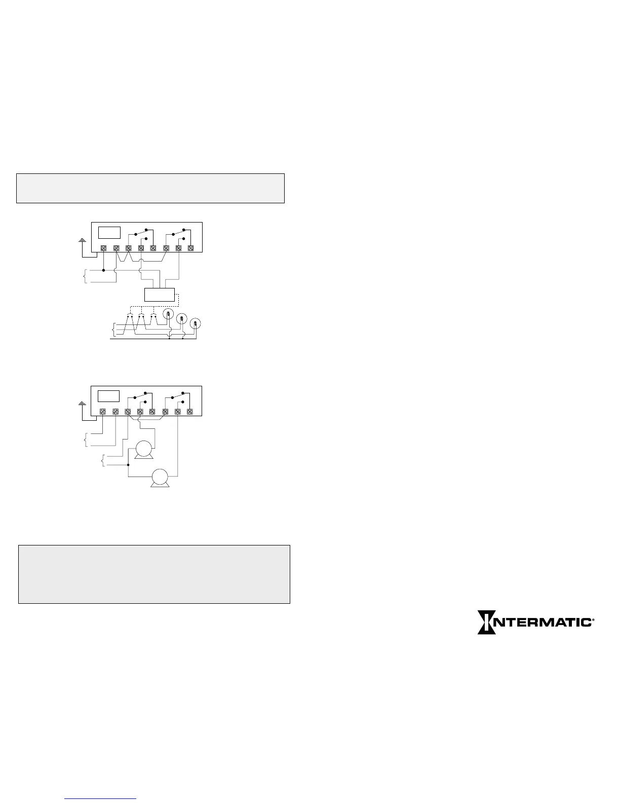
TYPICAL WIRING CONFIGURATIONS (24V Models)
NOTE: To enable switching loads of a voltage different than the timer
power voltage, the outputs from this timer are isolated relay contacts. You
need to connect a source of power to the common (COM) terminals as
shown above. Do not mix solid and stranded wires under the same
terminal.