GM40AVE SERIES TERMINAL DESIGNATIONS
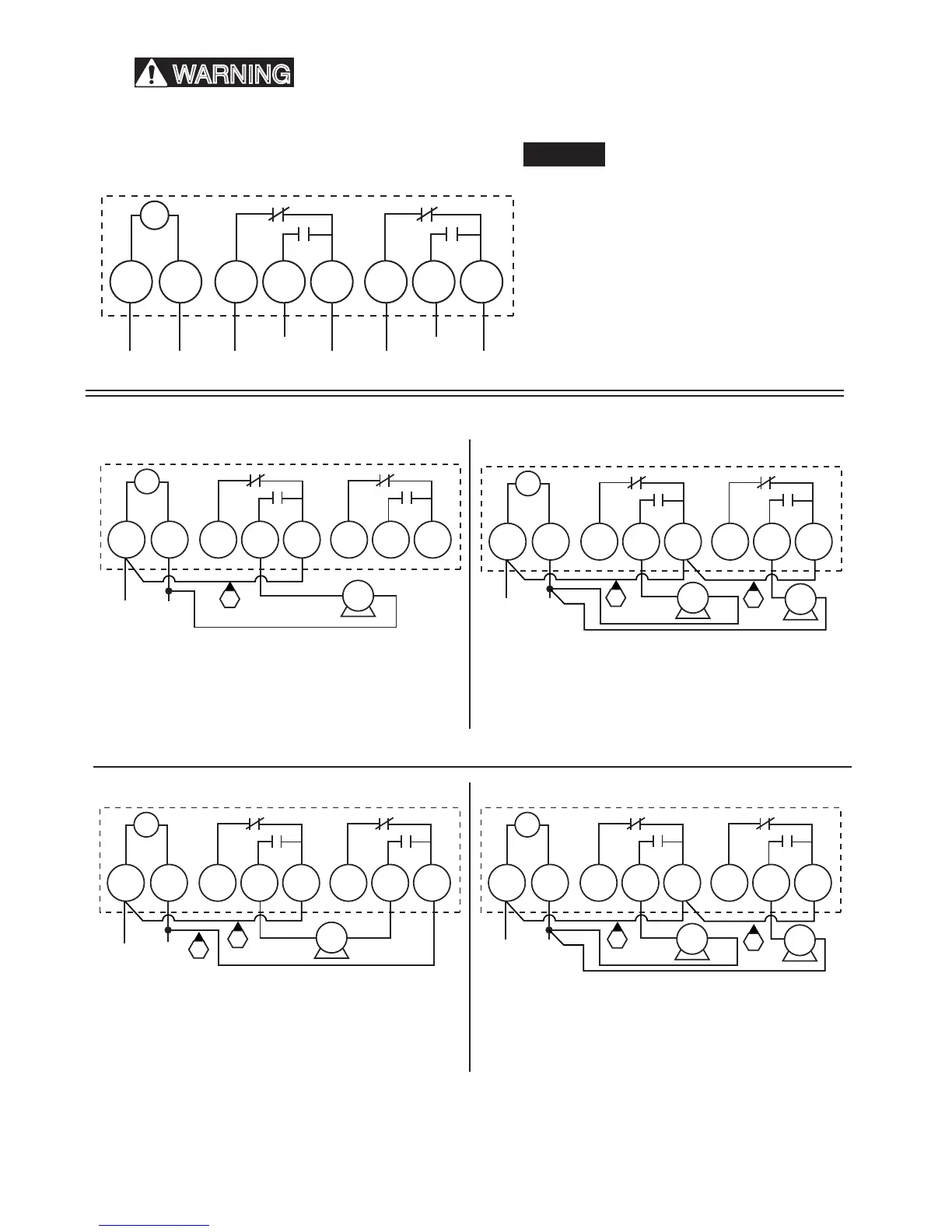
GM40AVE SERIES TYPICAL WIRING DIAGRAMS
COM2NO 2NC 2COMNONCL 2/NL 1
T
TIMER
When the GM40AVE is used to control a single phase 120
VAC load, connect a jumper wire (J1) between L1 and COM.
When the GM40AVE is used to control a single phase 240
VAC load, connect a jumper wire (J1) between L1 and COM
and connect a second jumper wire (J2) between L2 and
COM2.
When the GM40AVE is used to control two single phase 120
VAC loads, connect a jumper wire (J1) between L1 and COM
and connect a second jumper wire (J2) between COM and
COM2.
NOTICE! Make sure that the combined amperage of Load 1
and Load 2 do not exceed the limits of the feed circuit.
When the GM40AVE is used to control two single phase 277
VAC loads, connect a jumper wire (J1) between L1 and COM
and connect a second jumper wire (J2) between COM and
COM2.
NOTICE! Make sure that the combined amperage of Load 1
and Load 2 does not exceed the limits of the feed circuit.
COM2NO 2NC 2NONCL 2/NL 1
T
TIMER
L N
120VAC
COM
LOAD
J1
COM2NO 2NC 2NONCL 2/NL 1
T
TIMER
L1 L2
240VAC
COM
LOAD
#1
J1
J2
NO 2NC 2NONCL 2/NL 1
T
TIMER
L N
120VAC
COM
LOAD
#1
LOAD
#2
J1
J2
COM2
NO 2NC 2NONCL 2/NL 1
T
TIMER
L N
277VAC
COM
LOAD
#1
LOAD
#2
J2
J1
COM2
120 VAC One Load
240 VAC One Load
120 VAC Two Loads
277 VAC Two Loads
This Time Switch is designed to control one or two single phase loads. Do Not use to directly control
three phase loads. Consult a qualied electrician if you are required to control three phase equipment.
3
The circuit conductors shall have an ampacity not •
less than the maximum total load to be controlled.
For all connections, use min. 8 AWG wire for 40 A •
loads or 10 AWG for 30 A loads, min. 90
o
C (194
o
F) rating.
Over current protection shall have an interrupting •
rating sufcient for the application control circuit
voltage and the total load current of the equipment
being controlled.
A fuse or circuit breaker shall be connected in •
series with each ungrounded conductor (and shall
be able to simultaneously open each conductor).
Jumper wires are not included.•
NOTICE
WARNING