Do you have a question about the Intermatic MultiWave and is the answer not in the manual?
Form for registering the product warranty to activate coverage.
Crucial safety directives and warnings for product installation and operation.
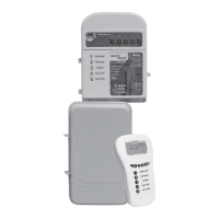
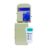
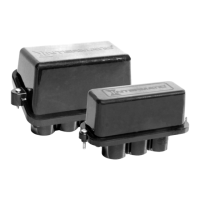
Detailed description of the various components within the MultiWave system.
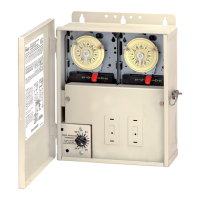
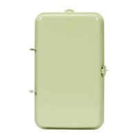
Step-by-step guide for installing the main PE653RC control system enclosure.
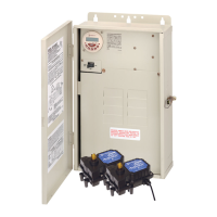
Procedure for securely mounting the PE30000 electrical load center.
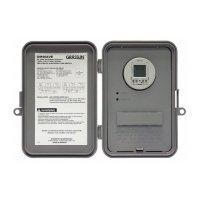
Instructions for attaching the PE653 receiver unit onto the load center.
Electrical specifications and contact ratings for the control system's loads.
Diagrams and guidance for wiring the system using 120-volt power sources.
Diagrams and guidance for wiring the system using 240-volt power sources.
Explanation of how power is supplied to and from the PE653RC receiver unit.
Steps to connect the P5043ME module's communication cable to the receiver.
Wiring details for power flow when using PE653RC with the P5043ME module.
Details on installing single-speed pool pumps with the control system.
Wiring diagram for connecting a 1-speed pump to the PE653RC receiver.
Wiring for 1-speed pumps on PE653RC when using the P5043ME expansion module.
Details on installing two-speed pool pumps with the control system.
Wiring diagram for connecting a 2-speed pump to the PE653RC receiver.
Wiring for 2-speed pumps on PE653RC with the P5043ME expansion module.
Information on connecting variable speed pumps to the control system.
How to connect Pentair VSP communication cable to the MultiWave receiver.
Guide for connecting variable speed pumps from other manufacturers.
Wiring instructions for connecting a 240V cleaner pump to the system.
Wiring diagram for connecting 120VAC lights, including GFCI or transformer.
Diagram showing how to connect actuators for pool/spa features to the P5043ME.
Wiring guide for connecting a single 240VAC heater to the PE653RC.
Wiring guide for connecting one or two heaters to the P5043ME module.
General guidelines for connecting heaters to the control system.
Specific wiring instructions for Jandy® brand heaters.
Specific wiring instructions for Raypak® brand heaters.
Specific wiring instructions for Hayward® brand heaters.
Specific wiring instructions for Pentair® brand heaters.
Wiring guide for Sta-Rite/Pentair heaters using the DDTC control board.
Wiring diagram for connecting a 240VAC blower to the PE653RC.
Wiring diagram for connecting a 240VAC cleaner pump or blower to PE653RC.
Wiring diagram for connecting a 240VAC blower to PE653RC and P5043ME.
Instructions for connecting chlorinator devices to the control system.
How to connect the AutoPilot SCG control cable to the MultiWave receiver.
Instructions for installing and connecting various system sensors.
Procedure for installing the water temperature sensor and connecting it.
Procedure for installing the freeze sensor and connecting it.
Procedure for installing the solar air temperature sensor and connecting it.
| Wireless Protocol | Z-Wave |
|---|---|
| Frequency | 908.42 MHz |
| Range | Up to 100 feet (30 meters) |
| Compatible Devices | Z-Wave enabled devices |
| Operating Temperature | 32°F to 104°F (0°C to 40°C) |