41 Heaters
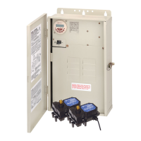
Connection for Raypak
®
Heaters
1. Remove power.
2. Connect two #14 gauge wires minimum, with an
insulation rating of 105°C, to terminals 8 and 9
on the PE653 (or to the Heater #1 or Heater #2
hookup when using P5043ME).
3. Route the wires through the low voltage knockout
in the PE653 (or P5043ME) enclosure.
4. Make sure that the Low Voltage Divider is in
place.
5. Connect the orange/black wire and the black/
orange wire to the wire from terminal 8 on the
PE653 (or from the hookup on the P5043ME).
6. Connect the yellow/black wire to the wire from
terminal 9 on the PE653 (or from the hookup on
the P5043ME). See Figure 6-4.
7. Re-apply power.
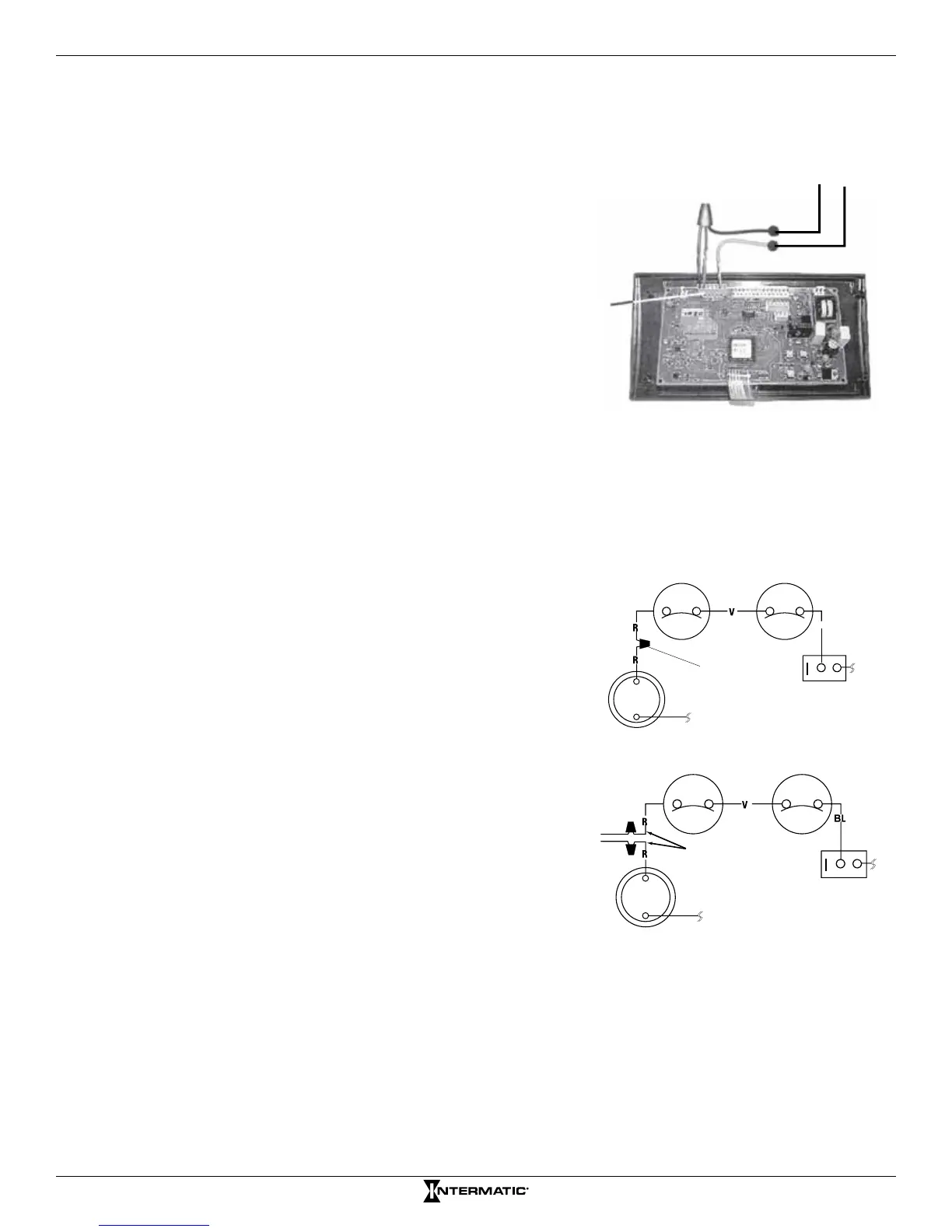
Connection for Hayward
®
Heaters
1. Remove power.
2. Connect two #14 gauge wires minimum, with
an insulation rating of 105°C, to
terminals 8 and
9 on the PE653 (or to the Heater #1 or Heater #2
hookup when using P5043ME).
3. Route the wires through the low voltage
knockout in the PE653 (or P5043ME) enclosure.
4. Make sure that the Low Voltage Divider is in
place.
5. Remove the heater service door.
6. Remove factory-installed wire nut between two
red wires labeled “CONNECTION FOR FIELD
INSTALLED CONTROL SWITCH.”
7. Wire nut the two heater wires from receiver (or
expansion module) to the two red wires of the
heater. See Figure 6-5.
8. Do not disconnect heater’s high limit or pressure
switches.
9. Set the thermostat selector switch to ON, HIGH, or SPA.
10. Set the heater thermostat(s) to maximum.
11. Replace service door.
12. Re-apply power.
BL
Figure 6-4. Typical wiring connections for Raypak Heaters.
Limit Switch Limit Switch
Limit Switch Limit Switch
Pressure Switch
Pressure Switch
Factory-
Installed
Wire Nut
Wires to
PE653
(or P5043ME)
OFF ON
OFF ON
Figure 6-5. Typical wiring connections for
Hayward
®
Heaters.
Wires from PE653
(or P5043ME)
P7
Terminal