www.intermatic.com
26
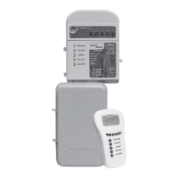
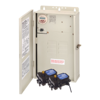
MultiWave Control System Installation Guide
2-Speed Pumps
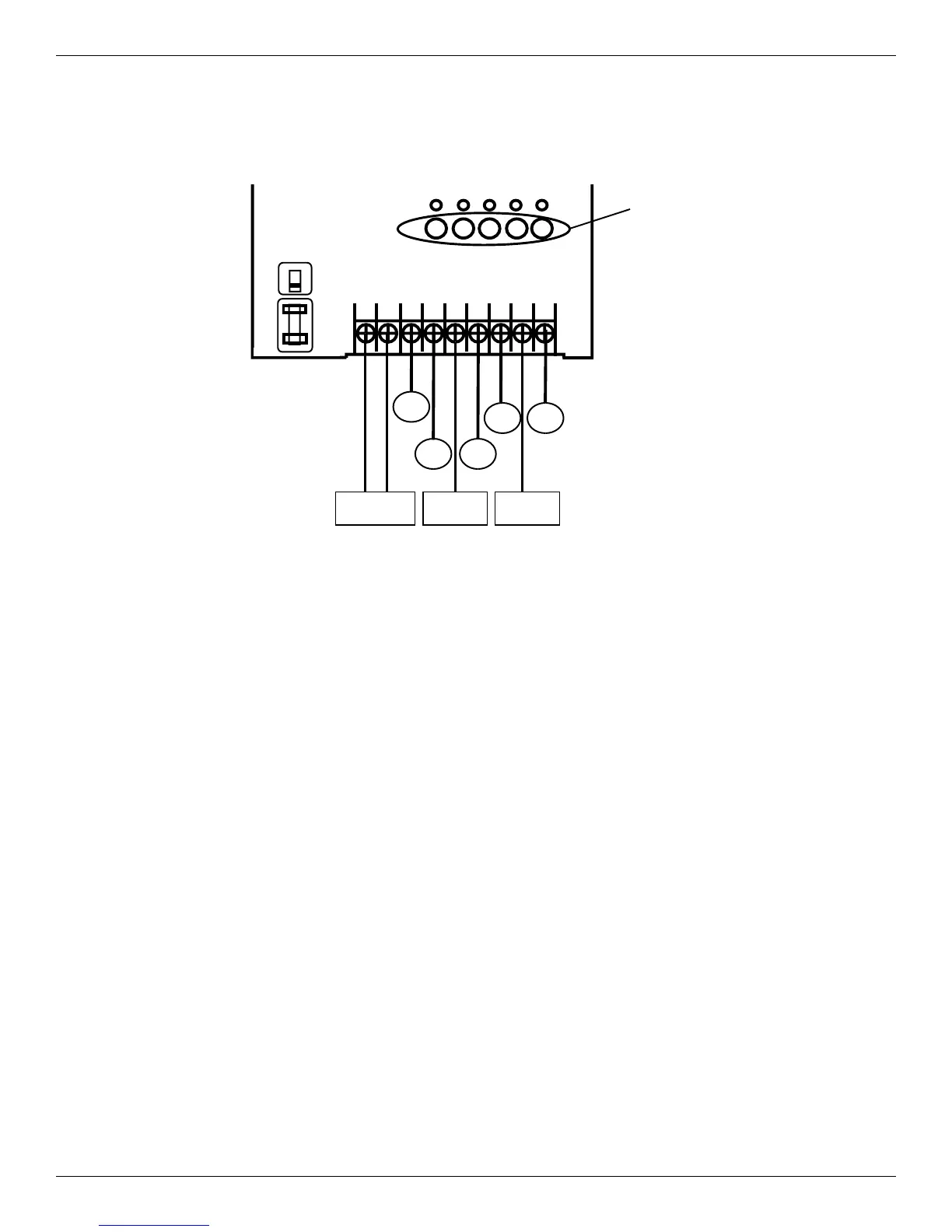
2-Speed Pump Terminal/Circuit Connections for PE653RC
123 4 5 6 7 8 9
1 2 3 4 5
Manual Circuit
OperationButtons
(Controls corresponding
numbered circuits below)
Circuit
1
Circuit
2
Circuit
3
Circuit
4
Circuit
5
Power In
120or240 VAC
L1 120
VACWire
L2
120V
240V
Terminals 1, 2 and 5 – Power In
Terminals 3 and 4, Circuits 1 and 2 – 240 VAC 2-Speed Pump*
Terminal 6, Circuit 3 – 240 VAC Blower*
Terminal 7, Circuit 4 – 120 VAC Light with GFCI*
Terminal 8/9, Circuit 5 – Heater**
* To break both lines, use relay kit PE21RLY. Request document 158--01559.
** See Chapter 6.
Figure 4-6. PE653 Receiver power terminal identification