17 Installing — Ratings, 120V/240V Wiring, Power In/Out
120V Wiring Applications
This Installation Guide covers most typical applications. If you need more instructions for 120V or
specic applications (i.e. water feature, auxiliary devices), please go to http://www.intermatic.com
to access the MultiWave Congurator for more wiring diagrams or call technical support for
assistance.
1 2
3
4
5
1234 56
78
9
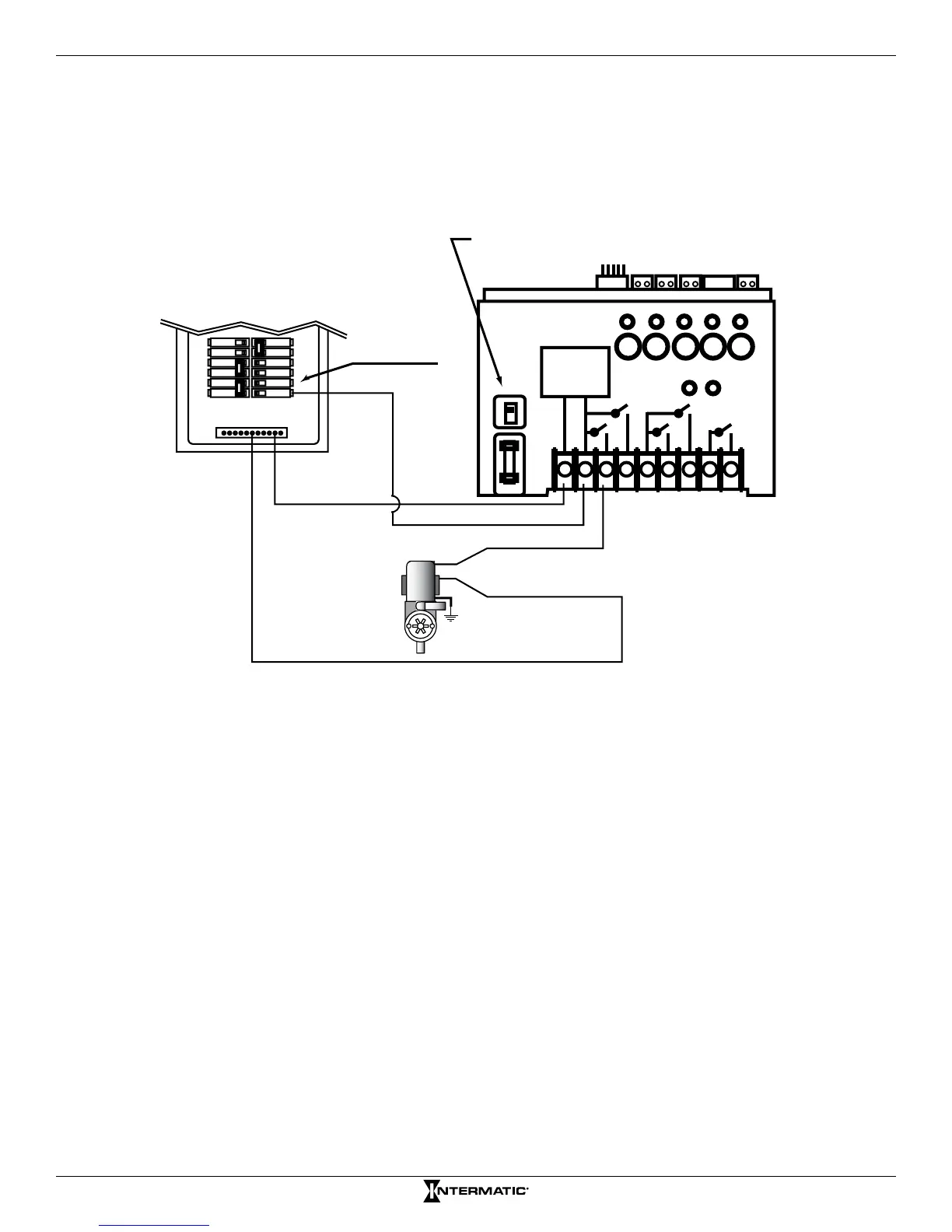
Make sure that voltage selector switch is in 120V position
before applying power to terminals 1 & 2
Select breaker to match wire size
and load requirement. Observe
maximum control circuit capacity.
Single Pole
Breaker
120 VAC
1-Speed Pump
(Circuit 1)
HOT (Circuit 1)
NEUTRAL
RECEIVER
POWER
SUPPLY
NEUTRAL BUS
120V
240V
Figure 3-2. Wiring for 120V 1-Speed Pump