www.intermatic.com
18
MultiWave Control System Installation Guide
12 34 5
123456789
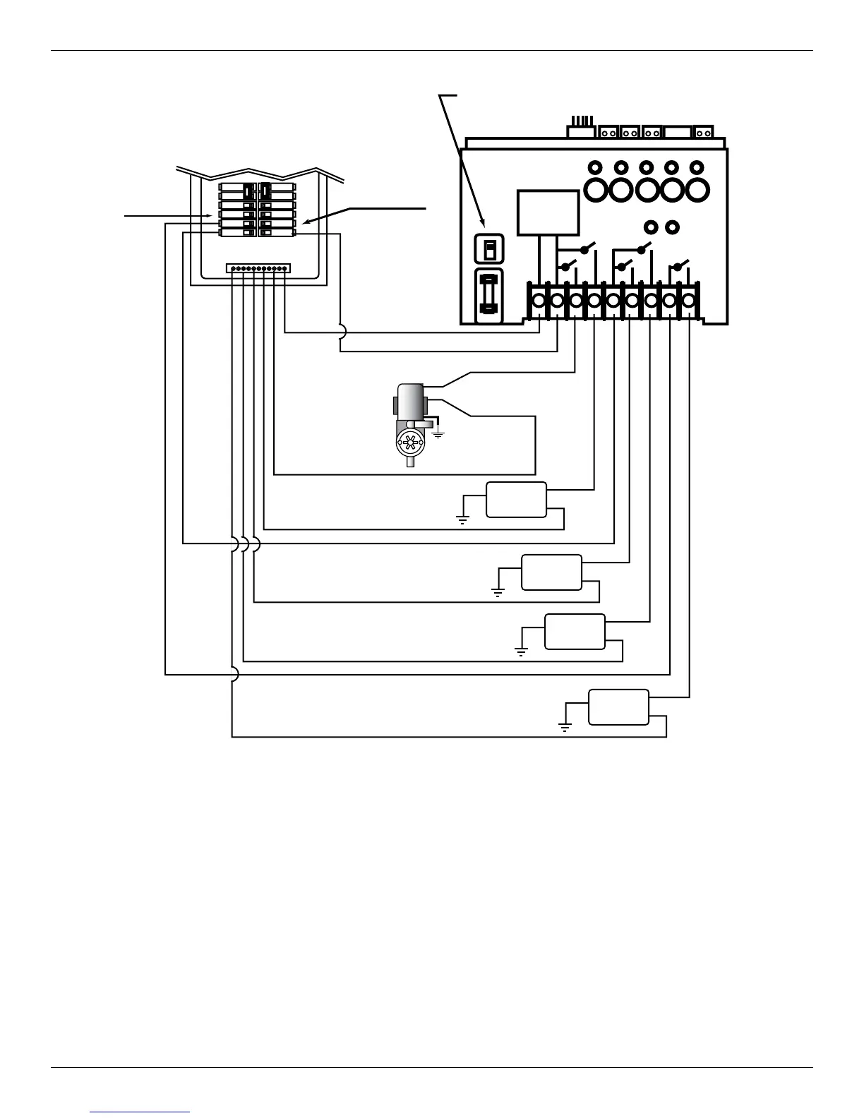
Make sure that voltage selector switch is in 120V position
before applying power to terminals 1 & 2
Select breaker to match wire size
and load requirement. Observe
maximum control circuit capacity.
1-Pole Breaker
1-Pole
Breakers
15 A. Max.
120 VAC
1-Speed Pump
(Circuit 1)
HOT (Circuit 1)
NEUTRAL
Aux.
(Circuit 2)
NOTE: The combined load on terminals 6 & 7
must NOT exceed 15 amps resistive
Aux.
(Circuit 3)
Aux.
(Circuit 4)
Aux.
(Circuit 5)
120 VAC
120 VAC
120 VAC
120 VAC
RECEIVER
POWER
SUPPLY
NEUTRAL BUS
120V
240V
Figure 3-3. Wiring for 120V 1-Speed Pump + Any 4 120V Auxiliary Components