Installation
Follow these instructions to install the timer switch.
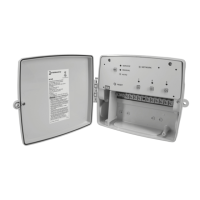
1. Open the Smart Wi-Fi Timer enclosure door.
2. Choose and remove the selected ½” to ¾” combination knockout(s) from the enclosure.
3. Place the enclosure in the desired location providing space for the enclosure door to swing open fully.
Note: Prior to installation, it is recommended to check your Wi-Fi signal strength at the desired installation location. A weak
signal strength could create intermittent Wi-Fi connection issues.
4. Mount the enclosure using hardware appropriate for the mounting surface (e.g., brick, concrete, drywall). We recommend using
two of the several 5 mm raised mounting locations in the back of the enclosure rather than the single-location hang slot.
(hardware not included) (Figure 1)
Note: Separation plate included in product for class 2 connections. Must not be removed.
LOCKING HASP
1/2", 3/4" DIA KO
(5 PLACES)
4.80"
4.00"
2.56"
Figure 1
5. Use appropriately rated ttings for the installation.
6. Strip ½” off the supply and load wires. Use AWG #14 - #8 copper conductors rated at least 105º C. Torque 10.6 to 15.6 Lb-In.
7. Connect the wires to the proper terminals on the Wi-Fi timer and tighten the screws rmly (See wiring diagram gures A and B).
8. Close enclosure door.
9. Apply power to the time switch.
10. Install ¼” Padlock thru hasp to secure if desired. (lock not included)
11. Device conguration are done using the Intermatic Connect mobile app. (available via the App Store and Google Play)
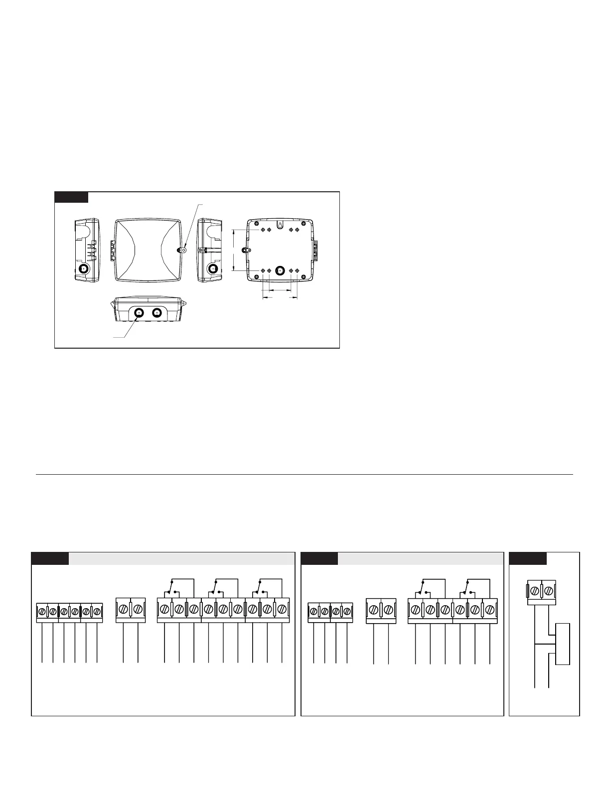
Wiring Diagrams
Figure A: 3 Circuit - 3xSPDT or 1xDPDT + 1xSPDT, Circuit 1 and Circuit 2 can be paired for DPDT applications
Figure B: 2 Circuit - 2xSPDT or 1xDPDT, Circuit 1 and Circuit 2 can be paired for DPDT applications
Figure C: Example of wiring a photocontrol, occupancy/vacancy sensor, or a single pole switch requiring a neutral.
Note 1: If using 277 VAC for the remote input terminals, Inputs 1 and 3
or Input 2 alone may be used on model PE733P
Note 2: For DPDT operations Circuit 1 and Circuit 2 will be paired
Note 3: If using 277 VAC for the remote input terminals,
Input 1 or Input 2 alone may be used on model PE723P
Figure A
120-277 VAC (For 277 VAC see note #1)
NC-1
NO-1 COM1
NC-2
COM2NO-2
CIRCUIT 1
OUTPUT 1
(NO)
INPUT 1
INPUT 2
COM3
INPUT 3
NO-3
NC-3
OUTPUT 1
(NC)
OUTPUT 2
(NO)
OUTPUT 3
(NO)
OUTPUT 2
(NC)
OUTPUT 3
(NC)
L1
POWER TO TIMER
L2/N
120/208/240/277 VAC
(AUTO VOLTAGE,
NO JUMPER REQUIRED)
POWER
TIMER
AC IN
SW3SW2SW1
CIRCUIT 2 CIRCUIT 3
REMOTE INPUT 1 L1
REMOTE INPUTS
REMOTE INPUT 1 N/L2
REMOTE INPUT 2 L1
REMOTE INPUT 3 L1
REMOTE INPUT 2 N/L2
REMOTE INPUT 3 N/L2
Figure B
120-277 VAC (For 277 VAC see note #3)
NC-1
NO-1 COM1
NC-2
COM2NO-2
CIRCUIT 1
OUTPUT 1
(NO)
INPUT 1
INPUT 2
OUTPUT 1
(NC)
OUTPUT 2
(NO)
OUTPUT 2
(NC)
L1
POWER TO TIMER
L2/N
120/208/240/277 VAC
(AUTO VOLTAGE,
NO JUMPER REQUIRED)
POWER
TIMER
AC IN
SW2SW1
CIRCUIT 2
REMOTE INPUT 1 L1
REMOTE INPUTS
REMOTE INPUT 2 L1
Figure C
120-277V
REMOTE INPUT
PHOTO CONTROL
OR OCC SENSOR
WHITE
RED
BLACK
POWER TO
PHOTO CONTROL
OR OCC SENSOR
N/L2
L1
 Loading...