Scan this qr code to download
the Intermatic Connect App via
the App Store and Google Play
Intermatic Connect App
Scan this qr code to access
the PE723P, PE733P
Programming Schedule Guide
Online Programming Schedule Guide
Smart Timer Network LED Table
Color – State Description
Off Wi-Fi and Bluetooth not connected
Red - Solid Ready for Wi-Fi and cloud operation but not
currently connected
Red – Slow Blinking System is updating
Blue - Solid Mobile app is connected via Bluetooth
®
wireless
Blue - Fast Blinking Mobile app is connected via Bluetooth
®
wireless and is communicating
Green - Solid Device is Cloud connected
Green - Blinking Cloud-enabled but currently ofine
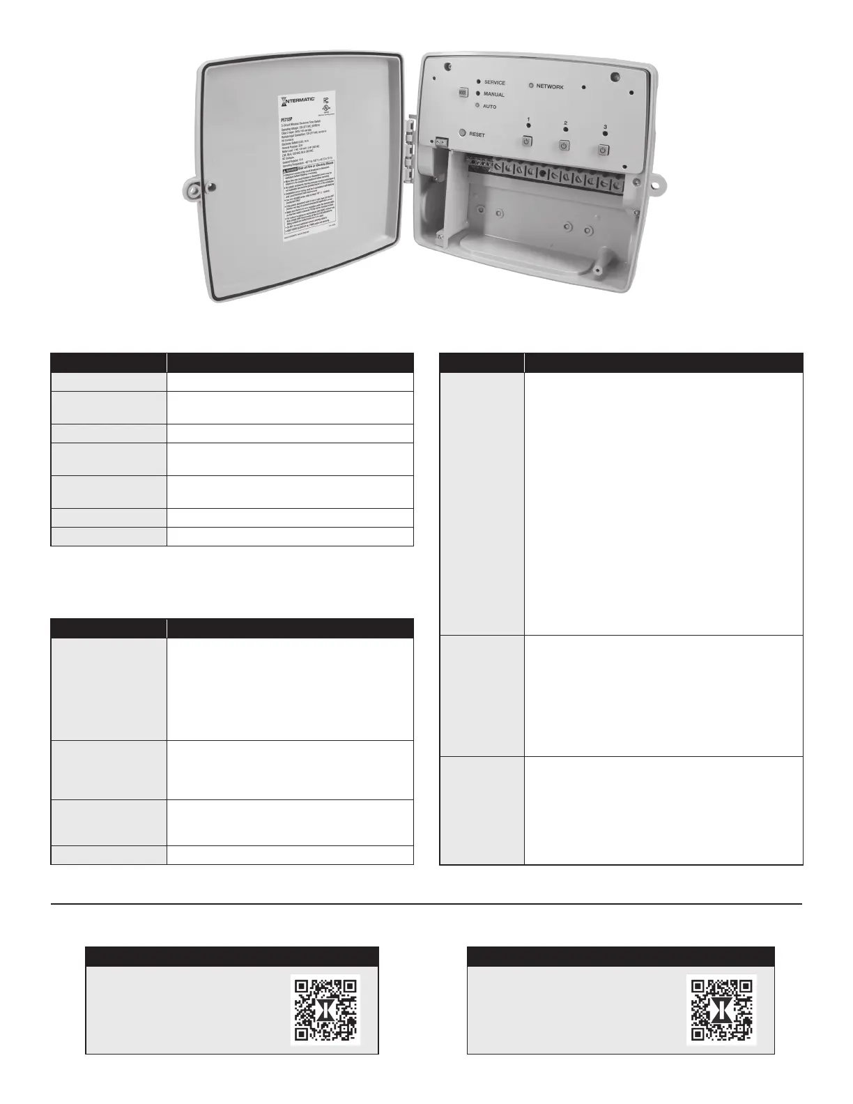
Smart Timer Mode LED Table
Mode (LED) Description
Manual Mode
(Yellow)
When power is applied to the device: the LED
shall be ON for approximately 1-second. At
which point, the LED will revert to its proper
state.
When the device is in Manual Mode this LED
will be On. When the device is in one of the
other modes, this LED will be Off.
Auto Mode (Green) When the device is in Auto Mode with an
active schedule running: the LED shall be On.
When the device is in the other modes, this
LED will be Off.
Service (Red) When the device is in Service Mode, this LED
will be On. When the device is in one of the
other modes, this LED will be Off.
Yellow Wink
Additional Information
Load LED Table
Circuits LED Description
L1 When Circuit 1 Normally Open (NO) circuit is
energized, LED L1 will be illuminated, when Circuit 1
Normally Closed (NC) Contact is energized, LED L1
will not be illuminated.
[Override] If Circuit 1 is overridden, LED L1 will
blink at a rate 1 second on and 1 second off for the
duration of the override.
Circuit 1 and 2 logically tied together:
If Circuit 1 and Circuit 2 are congured to work in unison,
LED L1 and L2 will be illuminated when both Circuits
1 and 2 Normally Open (NO) contacts are energized.
If Circuits 1 and 2 Normally Closed (NC) contacts are
energized, LED L1 and L2 will not be illuminated.
[Override]. If Circuit 1 or Circuit 1 and 2 are logically tied
together and is overridden (physical input 1, mobile or
Voice UI), LED L1 and LED L2 will blink at a rate 1 second
on and 1 second off for the duration of the override.
L2 When Circuit 2 Normally Open (NO) circuit is
energized, LED L2 will be illuminated, when Circuit 2
Normally Closed (NC) Contact is energized, LED L2
will not be illuminated.
[Override]. If Circuit 2 is congured to operate
independently and is overridden (physical input 2,
mobile or Voice UI), LED L3 will blink at a rate 1 second
on and 1 second off for the duration of the override.
L3 When Circuit 3 Normally Open (NO) circuit is
energized, LED L3 will be illuminated, when Circuit 3
Normally Closed (NC) Contact is energized, LED L3
will not be illuminated.
[Override]. If Circuit 3 is overridden (physical input,
mobile or Voice UI), LED L3 will blink at a rate 1 second
on and 1 second off for the duration of the override.
 Loading...