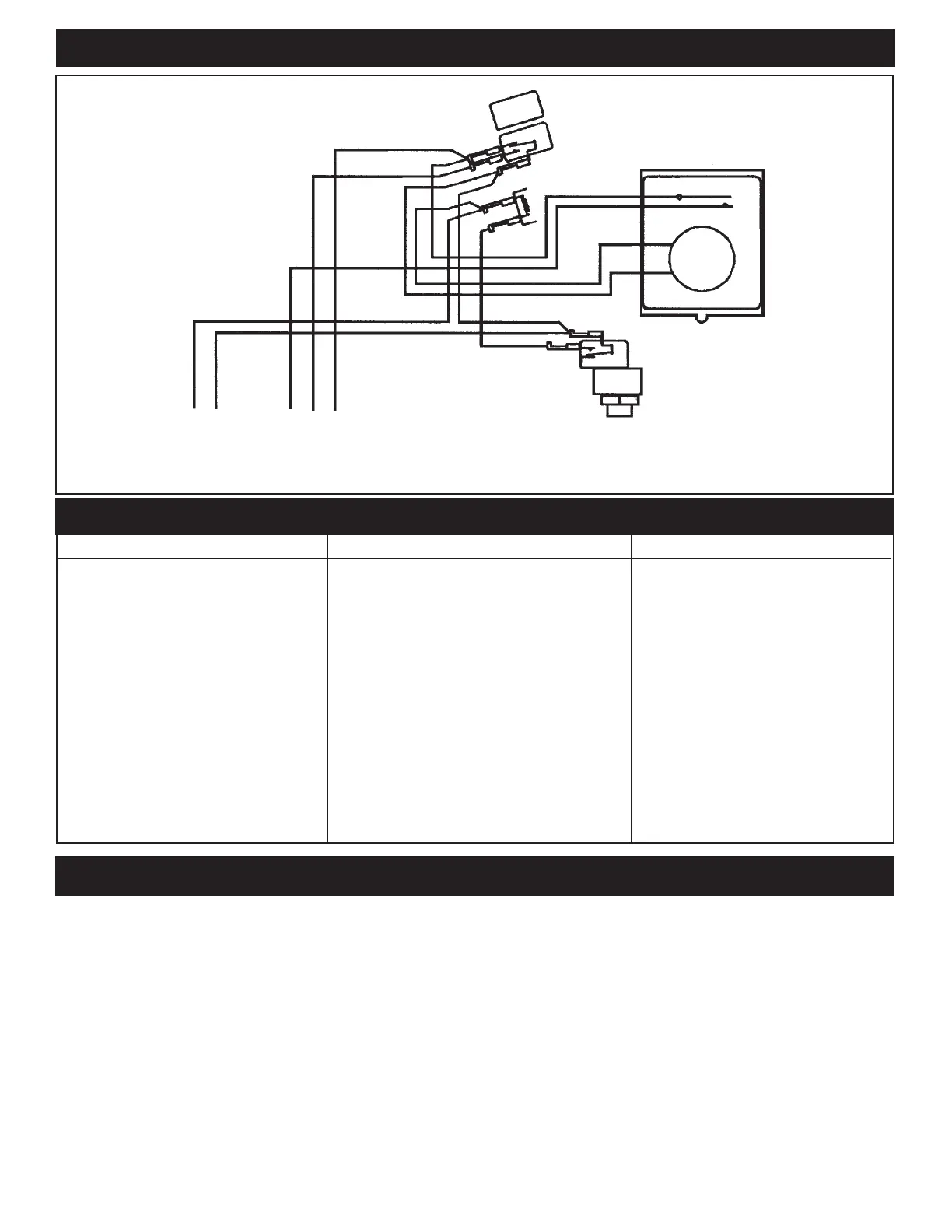
INTERNAL WIRING - MODEL RC2123PT
PULSE
SWITCH
RELAY
GRAY
BLUE
BROWN
WHITE
BLACK
N L
INPUT
LO HI FRZ
2 SPEED
PUMP
TROUBLESHOOTING
SYMPTOM CAUSE(S) CORRECTIVE ACTION
1.Pumpwillnotoperateoroperates 1a.Airhosedisconnected Checkhoseconnections.
on low speed only. 1b. Defective air button Replace air button - see note 1.
1c. Water in air hose Blow-out air hose - see note 2.
1d. Defective pulse switch Replace pulse switch - see note 2.
1e. Defective relay Replace relay - see note 3.
1f. Air button is too far Install larger air button.
2.Pumpwillnotturnofforoperates 2a.Airhosedisconnected Checkhoseconnections.
on high speed only. 2b. Defective air button Replace air button - see note 1.
2c. Defective relay Replace relay - see note 3.
3. Pump turns on/off by itself. 3a. Defective pulse switch Replace pulse switch.
3b. Water in air hose Blow-out air hose - see note 2.
3c. Changingairpressureinairhose Rerouteairhose.
4. Blank Timer Display during power 4a. Dead battery Replace battery.
failure
NOTES
A Pneumatic Remote Control (Air Switch) consists of an air button (air pump, transmitter), a pulse switch (air
Sensor, receiver) and a relay (either alternate action or stepper). The air button is connected to the pulse
switch by the air hose. By pressing on the air button at one end of the air hose, the increased pressure will
momentarily close the contacts of the pulse switch at the other end of the air hose, thus energizing the coil of
the relay. The relay turns ON or OFF the connected equipment.
1. An air button with ruptured seal or bellows inside, will not produce sufficient air pressure to operate the
momentary air switch and could lead to total break down.
2. Water in air hose will damage the pulse switch and it is caused by a faulty air button (see note 1 above) or
condensation. In either case, it must be drained and the cause found and corrected. To reduce condensa-
tion, protect the air hose from exposure to direct sun, ice or frequent temperature fluctuations.
3. A defective relay is either due to contact or coil failure. Contact failure is caused by over-load or cross-
wiring and coil failure is caused by 240 volt connected across the 120 volt coil or permanently applied 120
volt. (The relay is designed for intermittent duty only). Permanently applied 120 volt could be the result of
water in the air hose (see note 2 above) or a spa cover placed over (and depressing) the air button. In any
case, the cause must be found, corrected and the relay replaced.
3
TIMER
TIME
CLOCK
MOTOR
 Loading...