GPIO Terminal Block User’s Guide 11
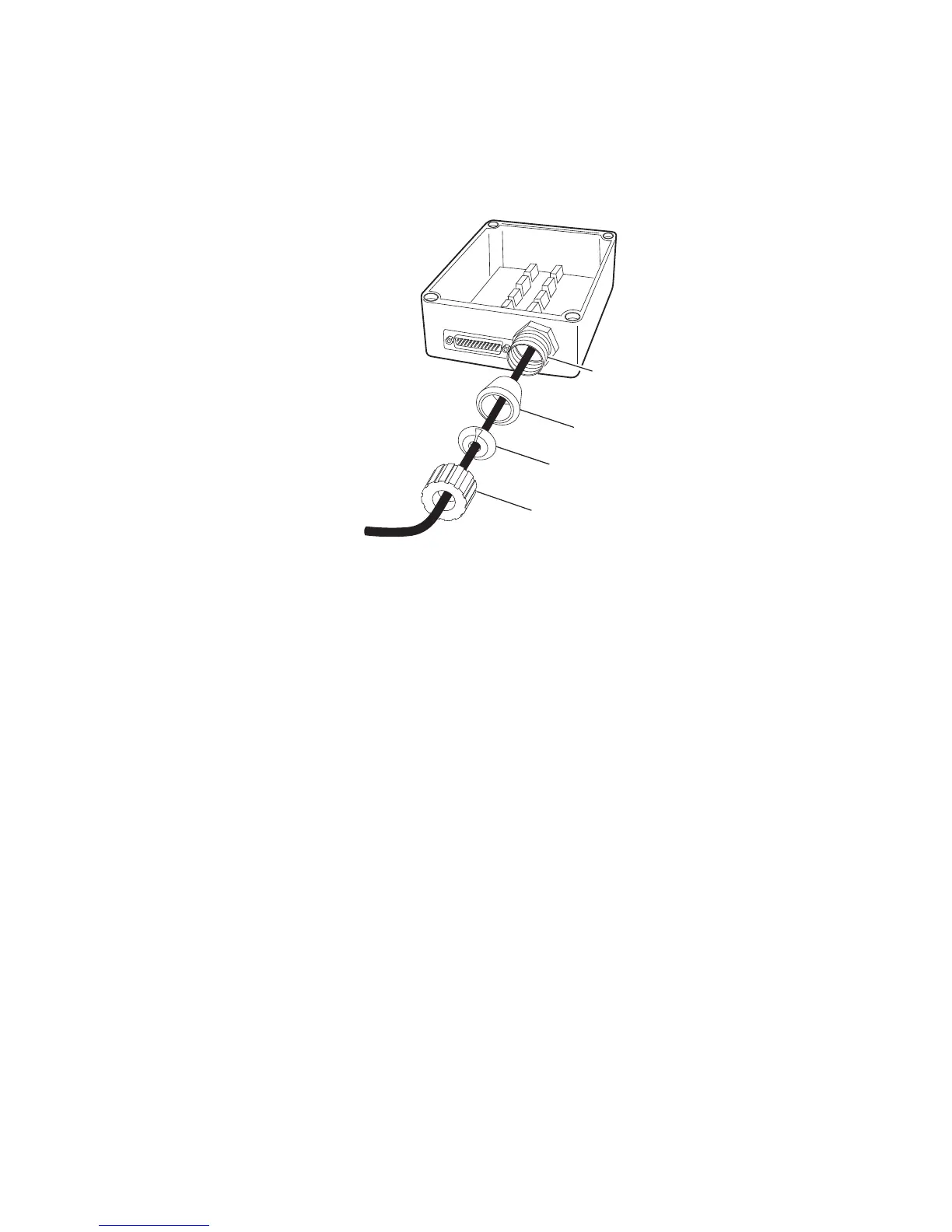
5 Route the control wiring through the sleeve, split ring, and
bushing, and into the terminal block through the strain relief
connector body.
6 Connect the control wiring to the appropriate terminals inside the
terminal block. For more information, see the next section,
“Connecting To the IF5, IF30, and IF61 Readers.”
7 Install the bushing, split ring, and sleeve on the strain relief
connector body (finger tighten only).
8 Install the top cover.
9 Connect the GPIO cable to the terminal block serial port and to
the reader as follows:
• For the IF61, connect the cable (P/N 236-057-001) to the GPIO
port.
• For the IF5 or IF30, connect the cable (P/N 236-057-001) to the
Control Port.
• For the IV7, connect the cable (P/N 236-089-001) to the Data
Port on the IV7 and to the COM port on the host PC.
Sleeve
Bushing
Split ring
Strain relief
connector body
To industrial
controls