EasyManua.ls Logo

International 710 - Page 32

International 710
48 pages
Print Icon
To Next Page IconTo Next Page
To Previous Page IconTo Previous Page
Loading...
SETTING
UP
ON-THE-LAND
OPERATION
-
Continued
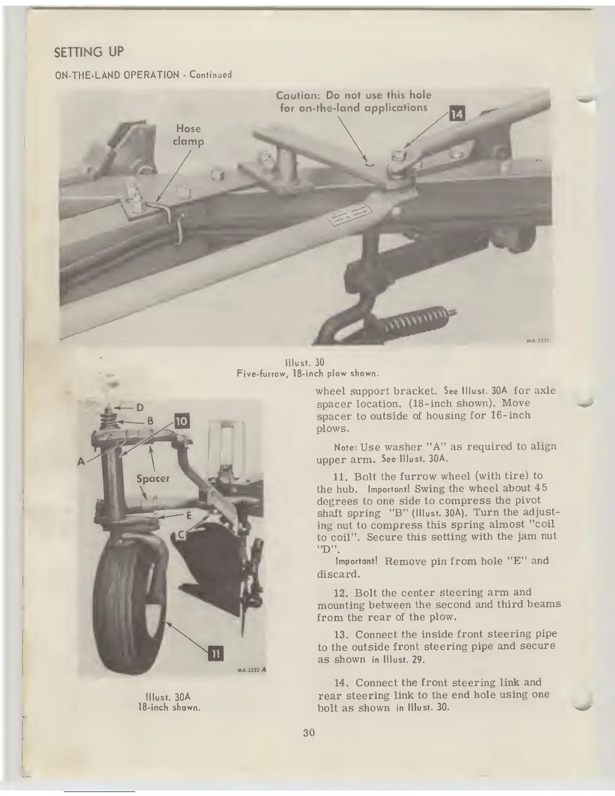
Caution:
Do
not
use
this
hole
for
on-the-land
applications
lllust.
30
Five-furrow, 18-inch
plow
shown.
wheel support
bracket. See lllust.
30A
for
axle
spacer
location.
(18-inch shown).
Move
spacer
to
outside of
housing
for
16-
inch
plows.
Note: Use
washer
"A" as
required
to
align
upper
arm.
See
lllust.
30A.
11. Bolt
the
furrow
wheel
(with
tire)
to
the hub.
Importont! Swing
the
wheel
about
45
degrees
to
one side
to
compress
the
pivot
shaft
spring
"B" (lllust.
30A).
Turn the
adjust-
ing nut to
compress
this
spring
almost
"coil
to
coil".
Secure
this
setting
with the
jam
nut
"D".
Important!
discard.
Remove
pin from hole
"E" and
«M-33tf A
lllust.
30A
18-inch shown.
12.
Bolt
the center
steering
arm
and
mounting
between
the second
and third
beams
from
the
rear of
the
plow.
13.
Connect
the inside
front
steering
pipe
to
the
outside
front
steering pipe
and
secure
as
shown
in
lllust.
29.
14.
Connect
the front
steering
link
and
rear
steering
link to the
end
hole
using
one
bolt as
shown
in
lllust.
30.
30

Table of Contents