EasyManua.ls Logo

International 710 - Page 33

International 710
48 pages
Print Icon
To Next Page IconTo Next Page
To Previous Page IconTo Previous Page
Loading...
SETTING
UP
ON-THE-LAND
OPERATION
- Continued
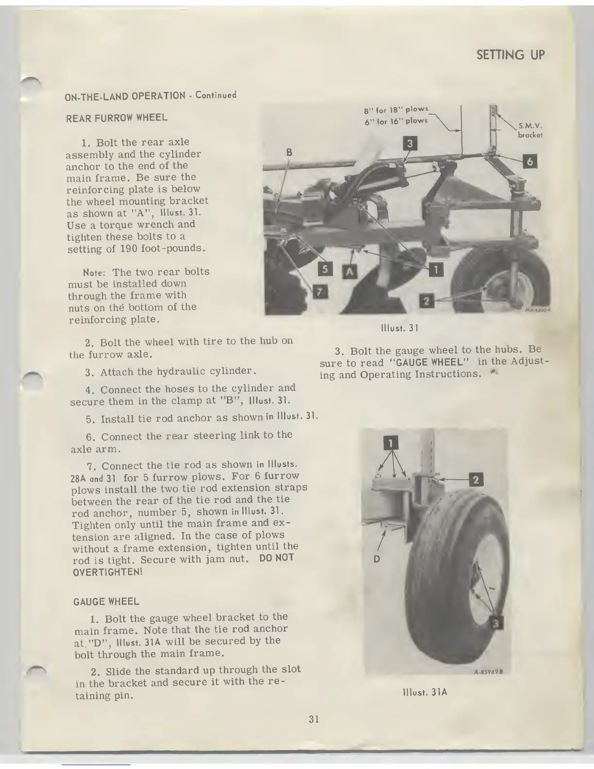
REAR
FURROW
WHEEL
1.
Bolt
the
rear
axle
assembly
and
the
cylinder
anchor
to
the
end
of
the
main
frame.
Be
sure
the
reinforcing
plate is
below
the
wheel
mounting
bracket
as
shown
at
"A",
lllust.
31.
Use
a
torque
wrench
and
tighten
these
bolts
to a
setting
of
190
foot-pounds.
Note:
The
two
rear
bolts
must
be
installed
down
through
the
frame
with
nuts
on
the
bottom
of
the
reinforcing
plate.
2.
Bolt
the
wheel
with
tire
to
the
hub
on
the
furrow
axle.
3.
Attach
the
hydraulic
cylinder.
4.
Connect
the
hoses
to
the
cylinder
and
secure
them
in
the
clamp
at "B",
lllust.
31.
5.
Install
tie
rod
anchor
as
shown
in
lllust.
31.
6.
Connect
the
rear
steering
link to
the
axle
arm.
7.
Connect
the
tie
rod
as
shown
in
lllusts.
28A
and
31
for
5 furrow
plows.
For
6
furrow
plows
install
the
two
tie
rod
extension
straps
between
the
rear
of
the
tie
rod
and
the
tie
rod
anchor,
number
5,
shown
in
lllust.
31.
Tighten
only
until
the
main
frame
and
ex-
tension
are
aligned.
In
the
case
of
plows
without
a
frame
extension,
tighten
until
the
rod
is
tight.
Secure
with
jam
nut.
DO
NOT
OVERTIGHTEN!
GAUGE
WHEEL
1.
Bolt
the
gauge
wheel
bracket
to
the
main
frame.
Note
that
the
tie
rod
anchor
at."D",
lllust.
31 A will
be
secured
by
the
bolt
through
the
main
frame.
2.
Slide
the
standard
up
through
the
slot
in
the
bracket
and
secure
it
with
the
re-
taining
pin.
31
8"
tor
18"
plows
6"
for
16"
plows
MA
4J<XM
lust. 31
3.
Bolt the
gauge
wheel
to
the
hubs.
Be
sure
to
read
"GAUGE
WHEEL"
in
the
Adjust-
ing
and
Operating
Instructions.
»
lllust.
31A

Table of Contents