EasyManua.ls Logo

International 710 - Page 34

International 710
48 pages
Print Icon
To Next Page IconTo Next Page
To Previous Page IconTo Previous Page
Loading...
SETTING
UP
AUTOMATIC RECOVERY
BEAMS
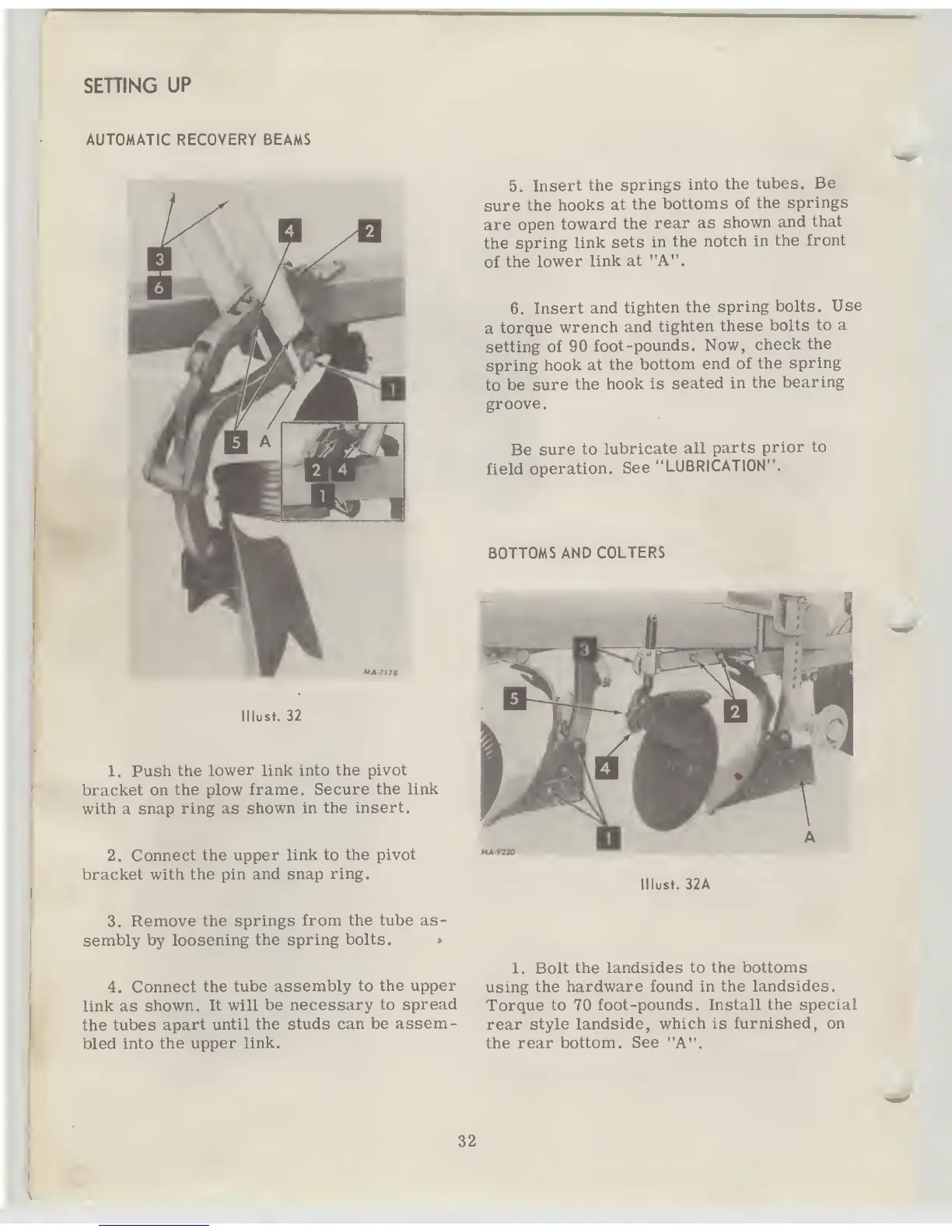
lllust. 32
1.
Push
the
lower
link into
the pivot
bracket on
the plow
frame. Secure
the
link
with
a
snap
ring
as
shown in the
insert.
2.
Connect
the
upper link to
the pivot
bracket with
the pin and
snap
ring.
5.
Insert
the
springs
into
the
tubes.
Be
sure
the
hooks
at
the
bottoms
of
the
springs
are
open
toward
the
rear as
shown
and
that
the
spring
link
sets
in
the
notch
in
the
front
of
the
lower
link
at "A".
6.
Insert
and
tighten
the
spring
bolts.
Use
a
torque
wrench
and
tighten
these
bolts
to a
setting
of
90
foot-pounds.
Now,
check
the
spring
hook
at
the
bottom
end of
the
spring
to
be
sure
the
hook
is
seated
in
the
bearing
groove.
Be
sure
to
lubricate
all
parts
prior
to
field
operation.
See
"LUBRICATION".
BOTTOMS AND
COLTERS
lllust.
32A
3.
Remove the
springs
from the tube as-
sembly by
loosening
the spring
bolts.
»
4.
Connect
the
tube
assembly to
the upper
link as
shown.
It will
be
necessary to
spread
the
tubes
apart
until
the studs can
be
assem-
bled into
the upper
link.
1.
Bolt
the landsides to
the bottoms
using
the
hardware found in the
landsides.
Torque
to 70
foot-pounds. Install the
special
rear
style landside,
which is
furnished, on
the
rear bottom.
See
"A".
32

Table of Contents