Home
Interpump
Power Tool
Hydralok HydraTouch H50
Page 26 (Electrical Diagram: 1 Phase)
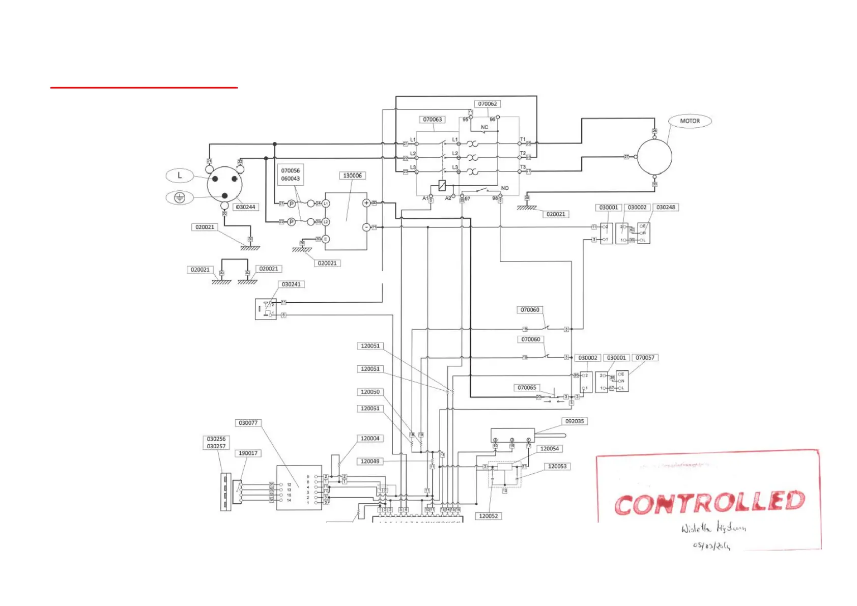
Interpump Hydralok HydraTouch H50 - Electrical Diagram: 1 Phase
26 pages
Manual
Save Page as PDF
To Previous Page
To Previous Page
Loading...
Ma
c
hines m
anuf
actured
by
Hydral
ok
,
Br
istol, UK
Ma
c
hine en
qu
ir
ie
s,
sa
le
s,
afte
r sa
le
s
servic
e :
Int
er
pump
H
yd
r
au
li
cs (UK
)
Ltd
t
/
a
I
M
M
Hydra
uli
cs (UK
)
:
Kidder
mi
nst
er
Te
l : (0)1
21
550 1
115 /
s
ale
s@i
mmh
yd
r
aul
ic
s.co
.
uk
26
Electrical Diagram: 1 Phase
25
Table of Contents
Main Page
Table of Contents
2
Warranty Conditions
3
Ec Declaration of Conformity
4
Safety Regulations
5
Technical / Dimensional Data
6
Handling/Transport
6
Preliminary Checks
6
Lighting
6
Routine Maintenance
6
Installation
7
Three Phase Machines
7
Single Phase Machines
7
Starting the Machine for the First Time
7
Safety Precautions
7
Basic Swaging Procedure
9
Basic Swage Screen
9
Important Note on Swage Dimensions
10
Quick Change Tool Operating Instructions
11
Inserting dies into the Machine
11
Advanced Swage Procedure
12
Swage Diameter
12
Swage Offset
12
Opening Time
12
Dwell
13
Preset Menu
14
CSV Table
14
Usb Updates
15
Settings Menu
16
Settings
16
Lubrication
17
Settings
19
Calibration
19
Help Screen
21
Technical Information
22
Maintenance and Service
22
Spare Parts
22
Die Fitting Instructions
24
Electrical Diagram: 3 Phase
25
Electrical Diagram: 1 Phase
26
Related product manuals
Hydralok HydraTouch H32
26 pages