English
57
SAVE THESE INSTRUCTIONS
English
(57) MODEL 603&637R FILTER PUMP ENGLISH 7.5” X 10.3” PANTONE 295U 05/28/2021
Page 5
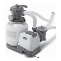
Be sure you have access to water to fill the pool and chemicals for the water.
IMPORTANT: This filter pump is shipped with the air release valve (1) open (open the air release
valve if necessary). DO NOT replace the air release valve until you reach STEP #8. Failure to follow
these instructions will result in air trapped inside filter housing; the motor will run dry, be noisy and
malfunction.
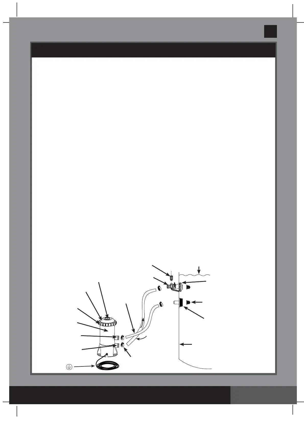
1.
Assemble above-ground-pool first. Carefully follow the pool’s installation instructions.
2.
Place the filter pump the length of the hose away from the pool wall where the lower black protruding
hose connection is "sticking-out".
3.
Insert the nozzle union
(13 & 10)
into the upper protruding hose connections, and then attach the pool
inlet air adaptor
(15)
to the upper protruding fitting. Screw the air jet valve
(14)
over the pool inlet air
adaptor
(15)
. Then insert the strainer union
(9 & 11)
into the lower protruding hose connections. The
hoses
(8)
fit over the strainers inserted into the connections.
4.
There are two hoses to be connected to the filter pump hose connections. With hose clamps
(7)
,
fasten one of the hoses
(8)
to the lower protruding hose connection (marked "+" on the pool liner) and
to the upper pump connection (marked "+").
5.
Connect the second hose to the pool inlet air adaptor
(15)
and to the lower pump connection. Make
sure all the hose clamps
(7)
are tight.
NOTE:
Make sure the air jet valve
(14)
is securely tighten onto
the pool inlet air adaptor
(15)
and facing up.
6.
In a counter-clockwise motion unscrew the threaded filter housing collar
(12)
from the filter housing.
Grasp and remove the threaded cover
(3)
. Check to see if a cartridge is inside the housing. If yes,
replace the cover, finger tighten the housing collar
(12)
back onto the filter housing.
7.
Fill the pool to a level of at least 1-2 inches above the top connection. The water will automatically flow
down into the pump.
8.
When water starts flowing out of the air release valve hole, screw in the air release valve back into the
filter housing cover. Do not over tighten the valve.
NOTE: Venting the system is necessary for air to
escape as the filter housing fills with water.
9.
Connect the filter pump to the power outlet and set the timer dial on the GFCI to the desired operating
hours. See the “Operating Time Table” section for the required operating hours related to each pool
size.
Note: If the End of Life (EOL) indicator on the GFCI plug is flashing, do not use the product.
Disconnect the product and have the GFCI plug replaced by a qualified electrician before using.
10.
Operate the filter pump until the desired water clarity is obtained.
Note:
Never put pool chemicals directly into the filter pump. This may damage the pump and void the
warranty.
SETUP INSTRUCTIONS
WATER LEVEL
POOL INLET NOZZLE
(REMOVE)
HOSE CLAMP
INSIDE OF POOL
STRAINER GRID (REMOVE)
PLUG
POOL INLET
AIR ADAPTOR
W
A
T
E
R
D
I
R
E
C
T
I
O
N
W
A
T
E
R
D
I
R
E
C
T
I
O
N
UPPER PUMP
CONNECTION
LOWER PUMP
CONNECTION
THREADED FILTER
HOUSING COLLAR
FILTER
CARTRIDGE
INSIDE
AIR RELEASE
VALVE
HOSE
FILTER HOUSING
COVER
AIR JET VALVE
(ILLUSTRATION NOT TO SCALE)