SECTION 2—PARTS AND INSTALLATION
Part No 1150695 15 Recessed Side Entry Bath Tubs
Installing the Tub
WARNING
Protective eye wear MUST be worn when drilling to avoid possible eye injury.
The tub MUST be supported by the floor and not the deck.
NOTE:Forthisprocedure,refertoFIGURE 2.2,FIGURE 2.3onpage16andFIGURE 2.4on
page16.
1. Carefullyremovethetubfromthecarton.
2. Inspectthetubforshippingdamageorfactorydefects.Ifdamageisfound,contactthe
shippingcarrier.
3. Measurethetub.
4. Ensuretheflooroftheinstallationlocationwillsupportthetub.
5. Determinewhethertheunitwillbebuiltagainstone,twoorthreewalls.
NOTE:FollowrecommendedfloorplanwheninstallingtubFIGURE 2.4.
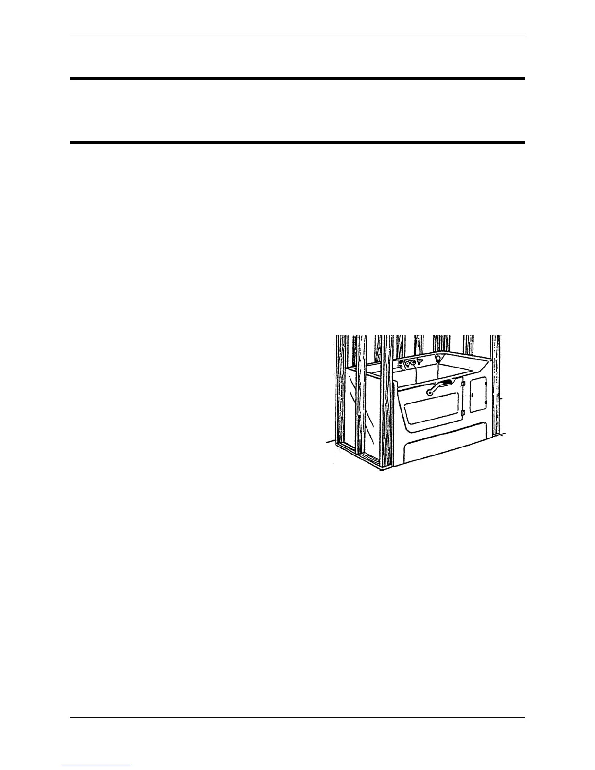
6. Threewallinstallationonly‐Ensureastudwall“pocket”hasbeenconstructedto
receivethetubunit.
NOTE:Ifdesired,awoodennailermaybe
attachedtostudwallsasanadditional
mountingfixtureforthetub.
NOTE:Theopeningofthe“pocket”shouldbe
sizedtoallowtheunittoslideineasily,without
anybindingbetweenthestudsandthetub
unit.Minorgapswillbecoveredbydrywallor
panelingduringthefinishingstage.In
remodelingsituationswheretub/showerunits
havebeenremoved,itmaybenecessaryto
modifytheopeningtoreceivethetub.
FIGURE 2.2 Stud Wall “Pocket”
7. Temporarilyslidetheunitintoplace.
8. Markthelocationofthefiberglasslipagainstthestuds.
9. Mount2‐inchx2‐inchcleatsapproximately1/8‐inchbelowthemarksmadein
STEP 8.
10. Ensurethecleatstonotinterferewithanycomponentsoftheunitorrestrict
installationinanyway.
11. Ensuretheplumbingandelectricallineshavebeenroutedtotheproperlocation.
12. Ensuretheunitislevelandplumb.
NOTE:Usea4‐footleveltolevelthetubfromfronttobackandsidetoside.