25
2.3.3 Axles
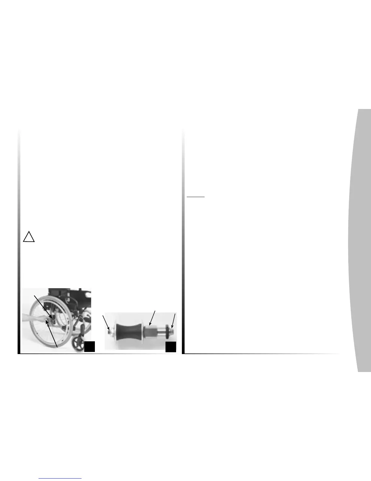
The axles connect the wheels and frame (photo 22).
Fixed (12" transit only) and quick-release axles are available
- Fixed axles: regularly check the axle tightening.
- Quick-release axles (photo 23) : depress the button (A) and
insert the axle in the wheel hub.
Position the assembly in the bearing (B) of the multiple adjus-
table wheel mounting until it locks in place. The locking balls
(C) must rise above the bearing. No signicant side clearance
is allowed.
To reduce clearance as much as possible, remove the axle and
adjust the nut using a 19 mm key ; then block the axle with an
11mm open-end key.
Make sure that the axle and the locking balls are clean.
(wipe out every month with a rag soaked with ne oil).
To prevent falls, it is essential that the button (A) and the
locking balls (C) are disengaged providing a perfect lock of the
rear wheels.
The quick release axle is a precision part, take care
of shocks and clean regularly to ensure the good working of the
mechanism.
2.4. Castors
2.4.1 8", 6" & 5" wheels
The front wheels are available in 8" (200mm) diameter and in
two widths, 1 3/8" (32 mm) and 2" (50mm), or in 6" (150mm)
diameter and a single width of 1 3/8" (32mm). They can be
delivered with pneumatic or solid tyre.
A 5" (100 mm) diameter soft roll (medium hard) is available.
Note : refer to paragraph 2.3.1. for regular maintenance.
2.4.2 Front fork
Different fork positions are available based upon the selection
of oor-to-seat height, castors and rear wheels.
i Please take advice from your dealer, if you want to replace
or remove the castors or rear wheels.
B
C
A
B
22
A
23