MK5
™
NX
™
- 80 ELECTRONICS 8-6 Part No. 1122140
OWNER’S SECTION I
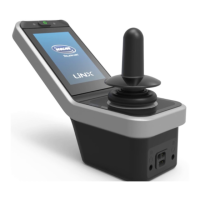
SPJ-80 JOYSTICK
SPJ-80 JOYSTICK
I. SPJ-80 JOYSTICK
- SWITCHES AND INDICATORS- SWITCHES AND INDICATORS
- SWITCHES AND INDICATORS- SWITCHES AND INDICATORS
- SWITCHES AND INDICATORS
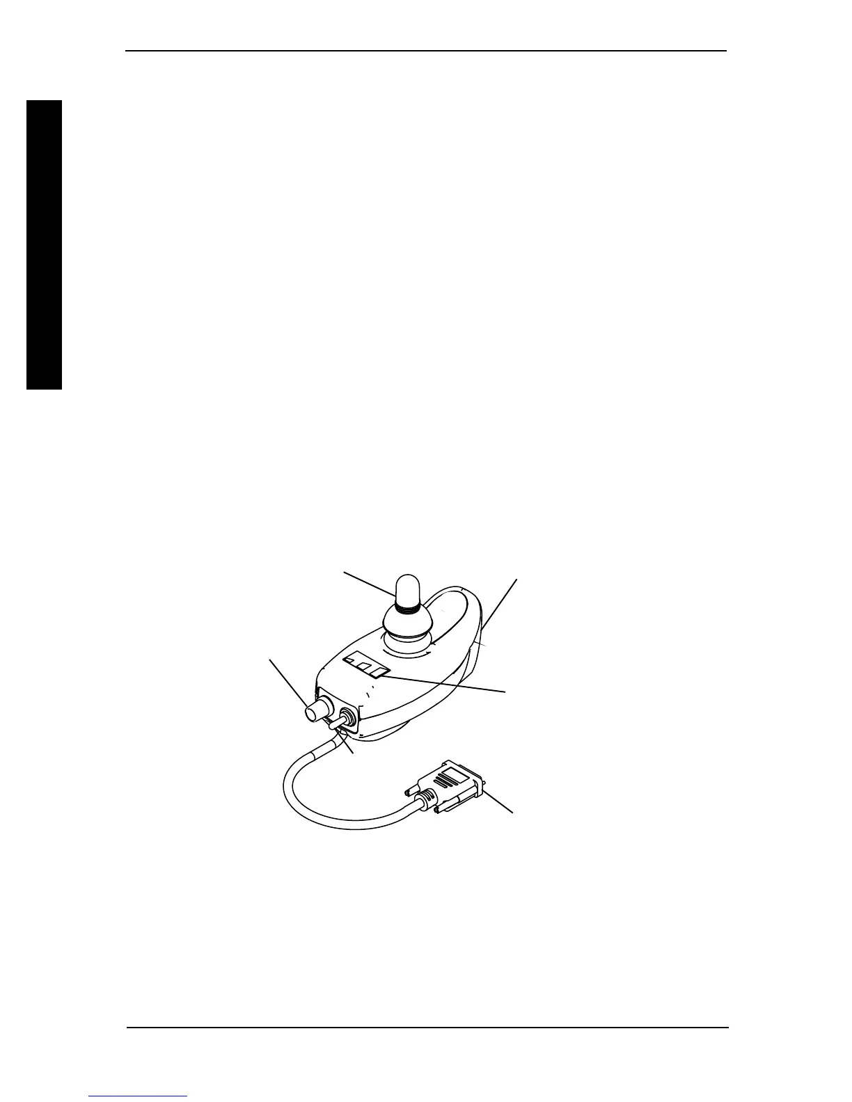
(FIGURE 1)(FIGURE 1)
(FIGURE 1)(FIGURE 1)
(FIGURE 1)
ON/OFF SWITCH - Two (2) position toggle is located at the back of the joystick housing.
SPEED CONTROL - Rotary knob is located on the back of the joystick housing. Turning
the knob clockwise increases the maximum speed of the chair.
JOYSTICK - Proportional drive control located at the front of the joystick housing pro-
vides smooth control of speed and direction.
BATTERY GAUGE DISPLAY (BGD) - Located at the rear of the joystick housing, it
provides information on the remaining charge in the batteries. At full charge all six (6)
segments of the bar graph are lighted; as the battery becomes discharged the farthest right
segment will go out until only the red bar is lighted; at this level the last red bar will start to
flash on and off to indicate that the user should charge the batteries as soon as possible.
The BGD also serves as a system diagnostic device when a fault is detected by the control
module. A specific number of flashes of the last two red bars (up to eight (8) flashes) will
start to flash on and off to indicate the type of fault detected separated by a pause. A chart of
the diagnostic indications is given in the DIAGNOSTIC CODE section of this manual.
Speed
Control
FIGURE 1 – SPJ-80 JOYSTICK
On/Off
Switch
To Controller
Joystick
Battery
Charger/
Programming
Port
Battery
Gauge
Display
 Loading...