33
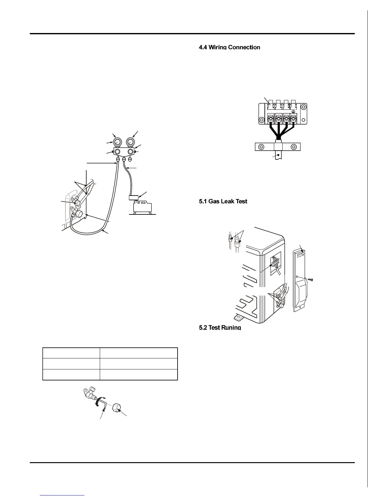
4. Operate the vacuum pump to begin evacuating. Perform evacu-
ating for about 15 minutes if the piping length is 20 meters (15
minutes for 20 meters) (assuming a pump capacity of 27 liters
per minute). Confirm that the compound pressure gauge read-
ing is –101 kPa (–76 cmHg).
5. Close the low pressure valve handle of gauge manifold.
6. Open fully the valve stem of the packed valves (both sides of
Gas and Liquid).
7. Remove the charging hose from the service port.
8. Securely tighten the caps on the packed valves.
CAUTION
IMPORTANT POINTS FOR PIPING WORK
1. Keep dust and moisture from entering the pipes.
2. Tighten connections carefully (between pipes and unit).
3. Evacuate the air in the connecting pipes using a VACUUM
PUMP.
4. Check for gas leaks at all connections.
Packed Valve handling precautions
• Open the valve stem all the way; but do not try to open it beyond
the stopper.
• Securely tighten the valve stem cap with torque in the following
table:
Compound
pressure
gauge
Pressure gauge
Manifold valve
Handle Hi
(Keep full closed)
Charge hose
(For R410A only)
Vacuum pump
adapter for
counter-flow
prevention
(For R410A only)
Packed valve
at liquid side
Packed valve at gas side
Service port
(Valve core (Setting pin))
Connecting
pipe
Handle Lo
Charge hose
(For R410A only)
-101kPa
(-76cmHg)
Vacuum
pump
1) Strip the insulation from the wire (20mm).
2) Connect the connection wires between the indoor and outdoor
units so that the terminal numbers match. Tighten the terminal
screws securely.
The screws are packed with the terminal board.
7.5 Test Operation
1. Check that all tubing and wiring have been properly connected.
2. Check that the gas and liquid side service valves are fully
open.
Check the flare nut connections for gas leaks with a gas leak
detector and/or soapy water.
1)Switch on power, press “ON/OFF” button on the wireless re-
mote control to start the operation.
2)Press MODE button, to select the COOL, HEAT (Cooling only
unit is not available), FAN to check whether the operation is nor-
mal or not.
Perform test operation and check items 1 and 2 below.
1. INDOOR UNIT
(1) Is operation of each button on the remote control unit normal?
(2) Does each lamp light normally?
(3) Do the air flow-direction louver operate normally?
(4) Is the drain normal?
2. OUTDOOR UNIT
(1) Is there any abnormal noise and vibration during operation?
(2) Will noise, wind, or drain water from the unit disturb the
neighbors?
(3) Is there any gas leakage?
Gas side (Ø9.52 mm)
Liquid side (Ø6.35 mm)
Service port
33 to 42 N
•
m (3.3 to 4.2 kgf
•
m)
14 to 18 N
•
m (1.4 to 1.8 kgf
•
m)
14 to 18 N
•
m (1.4 to 1.8 kgf
•
m)
Hexagon wrench(4mm)
Cap
23
Terminal block
Connecting cable
N(1)
Check places for
flare nut connections
(indoor unit)
Valve cover
Check places
for outdoor unit
Electric parts
Installation Manual
 Loading...