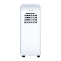
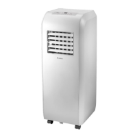
Europe
Part Description Quantity
Unit Adaptor
1 pc
Exhaust Hose
1 pc
*
Window Slider Adaptor
1 pc
*
Wall Exhaust Adaptor A
(only for wall installation)
1 pc
*
Wall Exhaust Adaptor B
(with cap) (only for wall
installation)
1 pc
*
Screw and anchor
(only for wall installation)
4 set
*
Window Slider A
1 pc
*
Window Slider B
1 pc
Power Cord Buckle
1 pc
Part Description Quantity
*
Bolt
1 pc
*
Security Bracket and Screw
1 set
Drain Hose
1 pc
Drain Hose Adaptor(only for
heat pump mode)
1 pc
*
Foam Seal A (Non- adhesive)
2 pc
*
Foam Seal B (Adhesive)
2 pc
*
Foam Seal C (Adhesive)
1 pc
Make sure the hook of the adaptor is aligned
with the hole seat of the air outlet.
Hook
Hole Seat
Lower groove
adaptor
Make sure the adaptor is
inserted into the lower
groove of the air outlet.
Window slider A
MODEL A
MODEL A
MODEL B
MODEL B
Window slider B
Bolt
Window slider A Window slider B
Bolt
or
or
Window slider A Window slider B
Window slider C
Bolts
Window slider A Window slider B
Window slider C
Bolts
Window Installation Kit
Step One: Preparation of the Exhaust Pipe
Apply pressure to the exhaust pipe and the window
adaptor one side, and the unit adaptor on the other, attach
with the use of the elastic buckles located on the adaptors.
Step Two: Install the Exhaust hose assembly to the unit
Insert unit adaptor of the Exhaust hose assembly into
the lower groove of the air outlet of the unit while the
hook of the adaptor is aligned with the hole seat of the
air outlet and slide down the Exhaust hose assembly
along the arrow direction for installation.
Step Three: Preparing the Adjustable Window Slider
1. Depending on the window size, make necessary
adjustments on the window slider.
2. If the length of the window requires two window
sliders, use the bolt to fasten the window sliders once
they are adjusted to the proper length.
3. For some models, if the length of the window
requires three window sliders(optional), use two bolts
to fasten the window sliders once they are adjusted to
proper length.
 Loading...