19
couplings serve as the connection.
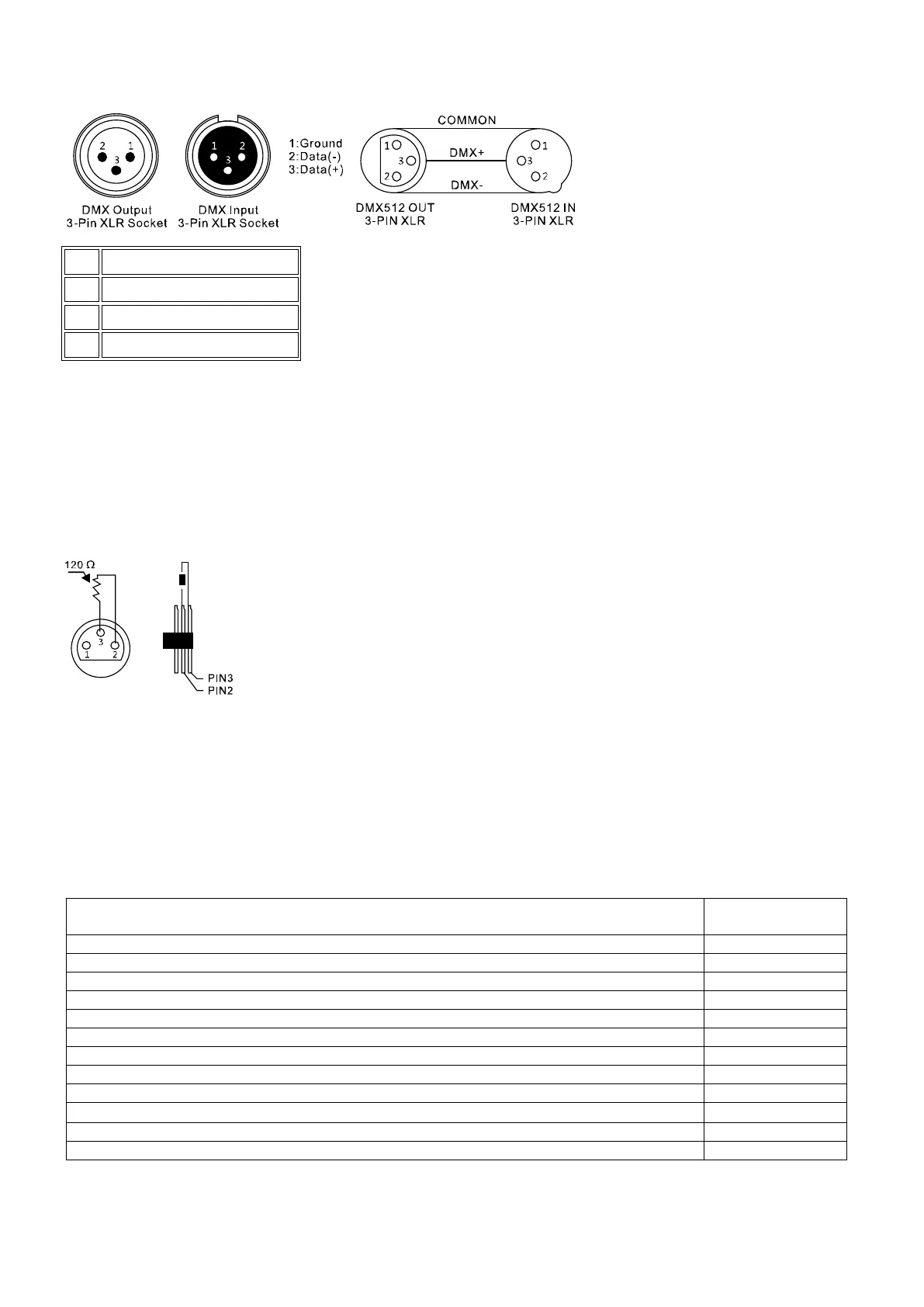
A three-pin XLR socket serves as a DMX output, a three-pin XLR plug serves as a DMX input.
Connect the DMX output of the DMX controller to the DMX input of the first DMX device. Connect the output of the
first DMX device to the input of the second and so on to form a series connection.
From a cable length of 300m or after 32 connected DMX devices, the signal should be amplified with the help of a
DMX splitter / repeater (e.g. Involight DMXS4, DMXS6 or DMXS8) to ensure error-free data transmission.
IMPORTANT: A terminating resistor should be connected to the last device in a DMX chain at the end of the chain.
DMX terminators are commercially available, but can also be built yourself. A 120 ohm resistor must be soldered
into an XLR connector between the two poles (+ and -).
2.2.3 Addressing the devices in the DMX chain:
The "EASYControl" assigns its DMX start addresses in steps of 16. This means that the devices must be set to the
corresponding start address so that the channel assignment of the faders is correct. Devices that get the same
start address naturally work synchronously with each other (example: devices 1 and 2 are both set to start address
1).
In order to explain:
DMX device (scanner, moving head, laser, light effect ...)
Starting address
to be set