EasyManua.ls Logo

INVT CHE100-2R2G-4 - User Manual

INVT CHE100-2R2G-4
124 pages
To Next Page IconTo Next Page
Loading...
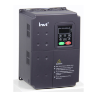
CHE Series Sensorless Vector
Control Inverter
Operation Manual
z Thank you very much for your buying CHE series sensorless vector control
inverter.
z
Before use, please read this manual thoroughly to ensure proper usage. Keep this
manual at an easily accessible place so that can refer anytime as necessary.

Table of Contents

Questions and Answers:

INVT CHE100-2R2G-4 Specifications

General IconGeneral
BrandINVT
ModelCHE100-2R2G-4
CategoryDC Drives
LanguageEnglish

Summary

Safety Precautions

Inverter Installation Guidelines

Inverter Wiring Procedures

Peripheral Device Connection

Illustrates the overall wiring diagram for connecting external devices.

Main Circuit Terminal Configuration

Shows the layout and labels of main circuit terminals for different inverter sizes.

Control Circuit Terminal Connections

Details the connection points and functions of control circuit terminals.

Typical Inverter Wiring Diagram

Presents a general wiring diagram for inverter connections with external components.

Component Specifications for Wiring

Lists specifications for breakers, cables, and contactors for various models.

Reactor Specifications

Provides specifications for AC input, AC output, and DC reactors.

Braking Unit and Resistor Specifications

Lists specifications for braking units and resistors, including order numbers.

Main Circuit Wiring: Input Side

Covers connections for breakers, contactors, AC reactors, and EMC filters.

Main Circuit Wiring: Inverter Side

Details wiring for DC reactors and braking units.

Main Circuit Wiring: Motor Side

Explains connections for output reactors and output EMC filters.

Regenerative Unit Wiring

Describes the wiring for a regenerative unit used for braking.

Common DC Bus Wiring Method

Explains the common DC bus method for multi-motor applications.

Ground Wiring (PE) Requirements

Provides guidelines for proper grounding of the inverter for safety.

Control Circuit Wiring Precautions

Offers recommendations for connecting control terminals and using shielded cables.

Control Circuit Terminal Functions

Lists terminal symbols and their functions for control circuits.

EMC Compliance Installation Guidelines

Grounding for EMC

Emphasizes the importance and methods of grounding for EMC and safety.

Inverter Operation and Interface

Operation Process: Parameter Setting

Guides the user through the process of setting inverter parameters via menus.

Fault Reset Procedure

Explains how to reset faults after an error occurs.

Motor Parameter Autotuning Process

Describes the procedure for tuning motor parameters for optimal performance.

Inverter Fault Information

Mentions the availability of fault information.

Detailed Function Parameters

P0 Group: Basic Functions

Explains basic functions like control mode and run command source.

P0.00: Control Mode Selection

Sets the inverter's control mode (SVC, V/F, Torque).

P0.01: Run Command Source

Selects the source for run commands (keypad, terminal, communication).

P0.03: Frequency Command Source

Defines the source for the frequency command.

P0.04: Maximum Frequency Setting

Sets the maximum output frequency limit.

P0.05: Upper Frequency Limit

Sets the upper limit for the output frequency.

P0.06: Lower Frequency Limit

Sets the lower limit for the output frequency.

P0.08: Acceleration Time 0

Defines the acceleration time from 0Hz to max frequency.

P0.09: Deceleration Time 0

Defines the deceleration time from max frequency to 0Hz.

P0.11: Carrier Frequency Setting

Sets the carrier frequency for PWM output.

P0.12: Motor Parameter Autotuning

Initiates motor parameter autotuning.

P1 Group: Start and Stop Control

Parameters for controlling motor start and stop operations.

P1.00: Start Mode Selection

Selects the starting method (direct start or DC braking start).

P1.01: Starting Frequency Setting

Sets the initial frequency for motor start.

P1.02: Starting Frequency Hold Time

Sets the duration for holding the starting frequency.

P1.03: DC Braking Current Before Start

Sets the DC braking current level before starting.

P1.04: DC Braking Time Before Start

Sets the duration for DC braking before starting.

P1.05: Stop Mode Selection

Selects the stop method (deceleration or coast to stop).

P1.06: DC Braking Starting Frequency

Sets the frequency at which DC braking starts.

P1.07: Waiting Time Before DC Braking

Sets a delay before DC braking begins.

P1.08: DC Braking Current

Specifies the DC braking current value.

P1.09: DC Braking Time

Sets the duration for DC braking.

P2 Group: Motor Parameters

Parameters for configuring motor characteristics for optimal performance.

P2.01: Motor Rated Power

Sets the motor's rated power.

P2.02: Motor Rated Frequency

Sets the motor's rated frequency.

P2.03: Motor Rated Speed

Sets the motor's rated speed.

P2.04: Motor Rated Voltage

Sets the motor's rated voltage.

P2.05: Motor Rated Current

Sets the motor's rated current.

P2.06: Motor Stator Resistance

Sets the motor's stator resistance.

P2.07: Motor Rotor Resistance

Sets the motor's rotor resistance.

P2.08: Motor Leakage Inductance

Sets the motor's leakage inductance.

P2.09: Motor Mutual Inductance

Sets the motor's mutual inductance.

P2.10: Motor Current Without Load

Sets the motor's current without load.

P3.00: ASR Proportional Gain Kp1

Sets the proportional gain for the Auto-tuning Speed Regulator (ASR).

P3.01: ASR Integral Time Ki1

Sets the integral time for the ASR.

P3.02: ASR Switching Point 1

Defines the frequency point for switching ASR parameters.

P3.03: ASR Proportional Gain Kp2

Sets the second proportional gain for ASR.

P3.04: ASR Integral Time Ki2

Sets the second integral time for ASR.

P3.05: ASR Switching Point 2

Defines the second frequency point for ASR parameter switching.

P3.06: Slip Compensation Rate (VC)

Adjusts slip compensation for vector control to improve speed precision.

P7.12-P7.14: Fault Type Recording

Records the most recent fault types for troubleshooting.

P7.15-P7.17: Fault Condition Data

Records operational data (frequency, current, voltage) at fault.

P7.18: Input Terminal Status at Fault

Records input terminal status during a fault.

P7.19: Output Terminal Status at Fault

Records output terminal status during a fault.

Troubleshooting: Faults and Solutions

Lists common fault codes, their reasons, and solutions.

Common Operational Faults and Solutions

Details common operational faults and their troubleshooting steps.

Troubleshooting: No Display on Power-On

Troubleshoots issues where the display is off after powering on.

Troubleshooting: Power Switch Tripping

Addresses tripping of the power supply air switch upon startup.

Troubleshooting: Motor Not Moving

Solves problems where the motor does not run after the inverter is on.

Troubleshooting: Input Switch Tripping During Operation

Troubleshoots input side switch tripping during inverter operation.

Inverter Maintenance Procedures

Outlines maintenance procedures and precautions.

P2 Group: Motor Parameters Configuration

Lists parameters for motor setup (P2.00-P2.10).

P3 Group: Vector Control Parameters

Lists parameters for vector control (P3.00-P3.07).

Related product manuals