EasyManua.ls Logo

INVT CHE100-5R5G/7R5P-4 - User Manual

INVT CHE100-5R5G/7R5P-4
124 pages
Print Icon
To Next Page IconTo Next Page
Loading...
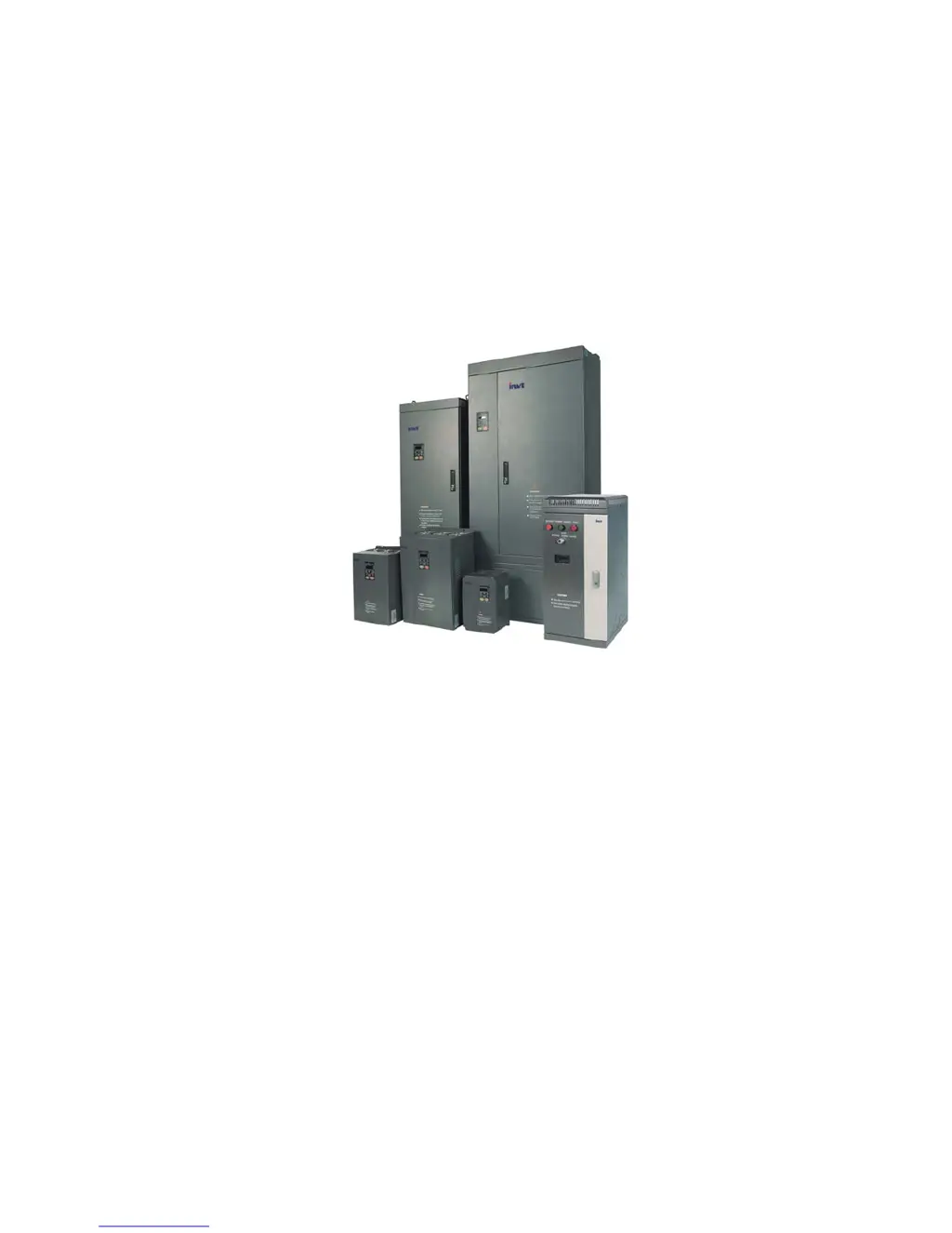
CHE Series Sensorless Vector
Control Inverter
Operation Manual
z Thank you very much for your buying CHE series sensorless vector control
inverter.
z
Before use, please read this manual thoroughly to ensure proper usage. Keep this
manual at an easily accessible place so that can refer anytime as necessary.

Table of Contents

Questions and Answers

  • E
    Elizabeth HuangAug 20, 2025
    What to do if there is over-current during acceleration in INVT DC Drives?
    • S
      Sandra MarshallAug 20, 2025
      If the INVT DC Drive displays an over-current error during acceleration, it could be due to several reasons. There might be a short-circuit or ground fault at the inverter output, the load could be too heavy, the acceleration/deceleration time might be too short, the V/F curve might be unsuitable, or there could be a sudden change in load. To resolve this: * Inspect the motor for damage, worn insulation, or cable damage. * Increase the acceleration/deceleration time or select an inverter with a larger capacity. * Check and adjust the V/F curve, and also check the load.
  • B
    Brady ThomasAug 22, 2025
    Why is my INVT CHE100-5R5G/7R5P-4 showing inverter overload?
    • S
      Scott TaylorAug 22, 2025
      If your INVT DC Drive displays an inverter overload, it could be due to a heavy load, short acceleration/deceleration time, an unsuitable V/F curve, or the inverter's capacity being too small. Here's how to address it: * Increase the acceleration/deceleration time or choose an inverter with a larger capacity. * Check and adjust the V/F curve. * Consider selecting an inverter with a higher capacity.
  • L
    Lance KnightAug 25, 2025
    How to fix IGBT Ph-U fault in INVT DC Drives?
    • P
      Paul BarnettAug 25, 2025
      If the INVT DC Drive shows an IGBT Ph-U fault, it could be due to several reasons: the acceleration/deceleration time being too short, a fault in the IGBT module itself, malfunction caused by interference, or improper grounding. To address this: * Increase the acceleration/deceleration time. * Inspect external equipment and eliminate any interference.
  • M
    Micheal JohnsonAug 26, 2025
    What causes over-voltage during acceleration in INVT CHE100-5R5G/7R5P-4?
    • C
      Catherine CrossAug 26, 2025
      If the INVT DC Drive shows an over-voltage error during acceleration, it could be due to a short deceleration time causing excessive regenerative energy from the motor, or the input voltage being too high. To fix this, you can: * Increase the deceleration time or connect a braking resistor. * Decrease the input voltage to stay within the specified range.
  • R
    rmyersAug 27, 2025
    Why is my INVT DC Drives showing motor overload?
    • B
      Bobby HarrisAug 28, 2025
      If the INVT DC Drive indicates a motor overload, it may be because the motor is driving a heavy load at low speed for an extended period, the V/F curve is not properly set, the motor’s overload protection threshold (PB.01) is incorrect, or there is a sudden load change. To resolve this: * Select a variable frequency motor. * Check and adjust the V/F curve. * Check and adjust PB.01. * Check the load.
  • C
    claire97Aug 29, 2025
    What causes DC bus Under-voltage in INVT CHE100-5R5G/7R5P-4 DC Drives?
    • J
      Jane WalkerAug 29, 2025
      If the INVT DC Drive displays a DC bus under-voltage error, it could be due to an open phase in the power supply, a momentary power loss, loose wiring terminals for the input power supply, or large voltage fluctuations in the power supply. Inspect the input power supply or wiring.
  • T
    tlopezAug 31, 2025
    What to do if INVT CHE100-5R5G/7R5P-4 shows input phase failure?
    • C
      Christopher Gordon IVAug 31, 2025
      If the INVT DC Drive shows an input phase failure, it could be due to an open phase in the power supply, a momentary power loss, loose wiring terminals for the input power supply, large voltage fluctuations in the power supply, or poor voltage balance between phases. Check the wiring, installation, and power supply.
  • M
    Margaret ElliottSep 2, 2025
    How to resolve rectify overheat in INVT DC Drives?
    • D
      Destiny AndersonSep 2, 2025
      If the INVT DC Drive displays a rectify overheat error, it could be due to high ambient temperature, proximity to a heat source, cooling fan issues (stopped or damaged), obstructed ventilation, or a high carrier frequency. To solve this: 1. Install a cooling unit. 2. Remove any nearby heat sources. 3. Replace the cooling fan. 4. Clear any obstructions in the ventilation channel. 5. Decrease the carrier frequency.
  • V
    vbryanSep 4, 2025
    What causes output phase failure in INVT CHE100-5R5G/7R5P-4 DC Drives?
    • C
      Crystal RodriguezSep 4, 2025
      If the INVT DC Drive indicates an output phase failure, it could be due to a broken wire in the output cable, a broken wire in the motor winding, or loose output terminals. Check the wiring and installation.
  • A
    Andrew BradySep 6, 2025
    How to troubleshoot communication fault in INVT CHE100-5R5G/7R5P-4 DC Drives?
    • R
      Reginald RogersSep 6, 2025
      If the INVT DC Drive displays a communication fault, it may be due to an incorrect baud rate setting, receiving incorrect data, or a prolonged interruption in communication. To solve this, set the proper baud rate and check the communication devices and signals.

Summary

Introduction

Safety Precautions

WARNING

Indicates a potentially dangerous situation resulting in death or serious injury.

CAUTION

Indicates a potentially dangerous situation resulting in minor injury or device damage.

Wiring

Typical Wiring Diagram

Presents a general schematic for connecting the inverter.

Wiring Main Circuits

Details how to connect the primary power and motor circuits.

Wiring Control Circuits

Explains the procedures for connecting control signals and inputs/outputs.

Operation

Detailed Function Description

P1 Group-Start and Stop Control

Manages how the inverter starts and stops the motor.

P2 Group-Motor Parameters

Input essential motor specifications for optimal performance.

P3 Group-Vector Control

Adjusts parameters for advanced vector control operation.

P4 Group- V;F Control

Configures the Voltage/Frequency control method and parameters.

PB Group- Protection Function

Configures various protection mechanisms like overload and stall protection.

Trouble Shooting

Fault and Trouble shooting

Lists fault codes, their reasons, and troubleshooting solutions.

Common Faults and Solutions

Provides common operational issues and their remedies.

Maintenance

List of Function Parameters

INVT CHE100-5R5G/7R5P-4 Specifications

General IconGeneral
ModelCHE100-5R5G/7R5P-4
Control MethodV/F control, Sensorless Vector Control
Overload Capacity150% for 60 seconds
Frequency Range0-400 Hz
Communication InterfaceRS485, Modbus
Cooling MethodForced Air Cooling
Enclosure RatingIP20
Voltage380-480V
Protection FeaturesOvercurrent, Overvoltage, Undervoltage, Overheating, Short Circuit
Operating Temperature-10°C to +40°C
Storage Temperature-20°C to +60°C
Humidity5% ~ 95% RH, non-condensing
Altitude≤1000m above sea level
Power5.5kW (G type), 7.5kW (P type)
Output Current12A/16A
Input Voltage3-phase 380-480V AC, 50/60Hz

Related product manuals