Operational manual for dynamic braking unit
-11-
5 Installation of the dynamic braking unit and parameters
setting
5.1 Wiring diagram
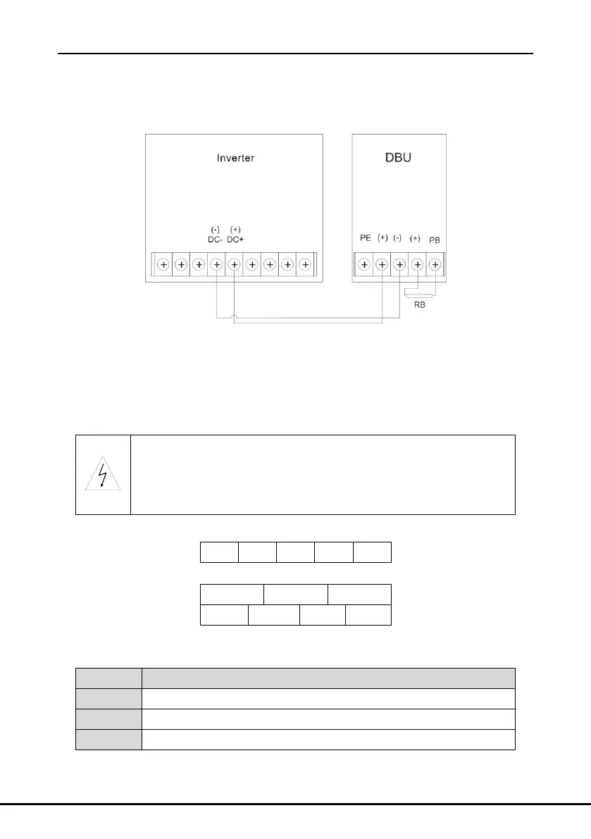
Figure 4 Wiring diagram of the main circuit between the dynamic braking unit and the DBU
Note:
The wiring between the DBU and the dynamic braking unit is less than 5m.
The wiring between the braking resistor and the braking unit is less than 10m.
DC+ and DC- are the “+”“-” of the internal DC bus in the DBU. DC+ is the positive pole and
DC- is the negative pole.
Wrong wiring of the main circuit may cause damage to the DBU and the
braking unit.
Do not touch the terminals of the control board when the machine is
powering on.
5.2 Terminals of the main circuit
Figure 5 Terminals of main circuit 60A-220A
Figure 6 Terminals of main circuit 320A~400A
Functions description:
Input terminal of the DC bus
External braking resistor terminal
Grounding terminal. Each machine should be grounded.

 Loading...