Operational manual for dynamic braking unit
-14-
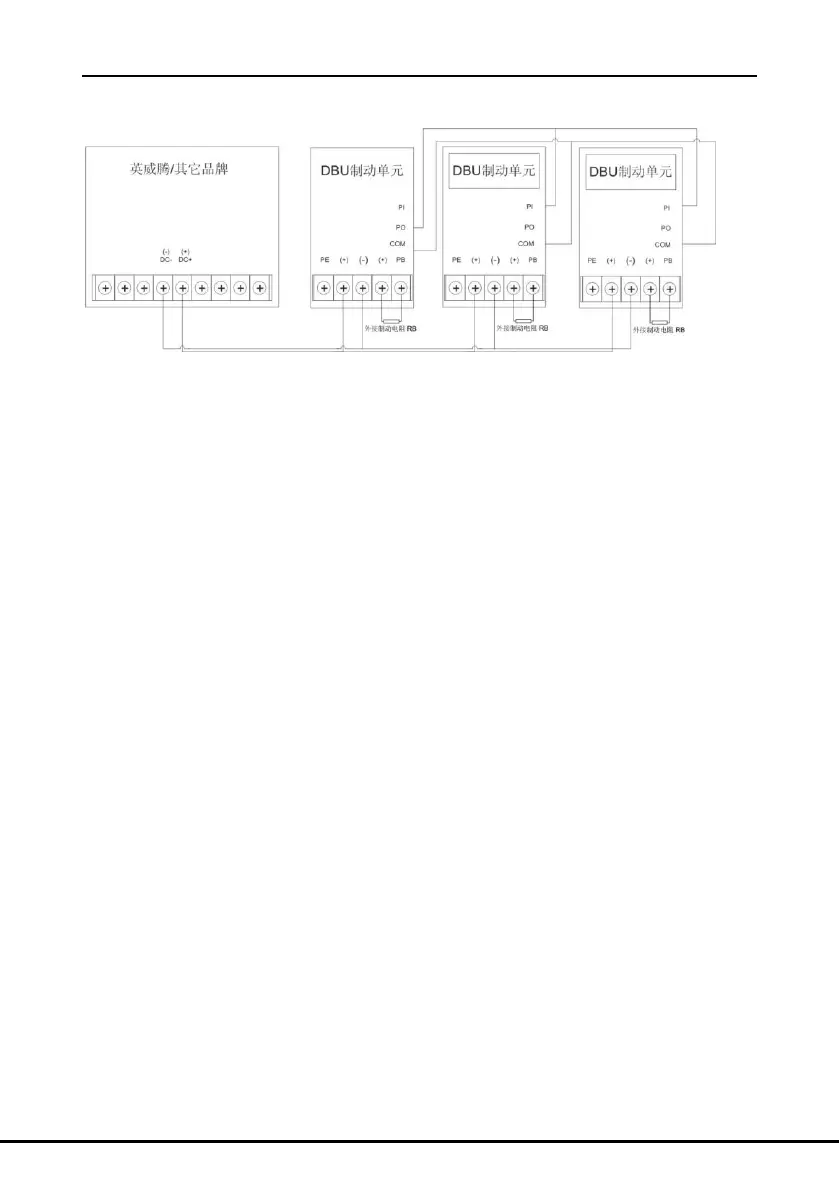
6 Parallel running
Figure 7 Wiring diagram between the parallel running braking units and the DBU
Please connect the DBU, multiple braking units and the braking resistor according to figure 7.
Wiring of the control terminals: when parallel braking units are put into use, the first one is the
master and the others are the slaves. The parameters setting of the slave are referred to the
section 9 of “braking threshold” and the braking rate of the master and the slave need to be
kept the same. The PO and COM terminal of the first braking unit is connected to the PI and
COM terminal of the second braking unit and the PI and COM terminal of the third braking unit
and so forth, the running of the whole parallel braking unit system can be monitored.

 Loading...