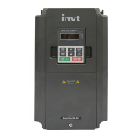
Do you have a question about the INVT GD10-2R2G-S2-B and is the answer not in the manual?
Defines terms like Danger, Warning, Note, and Qualified electricians for safety.
Explains warning symbols used in the manual for safety.
Outlines general safety rules for operating the VFD.
Provides safety guidelines for handling and installing the VFD.
Safety precautions for VFD commissioning and operation.
Safety guidelines for VFD maintenance and component replacement.
Guides users through initial steps for using the VFD.
Steps for initial VFD setup before actual operation.
Details technical specifications of the VFD.
Lists the VFD's rated electrical parameters.
Covers the physical aspects of installing the VFD.
Details requirements for the VFD's installation location.
Covers wiring and electrical connections for the VFD.
Guides on wiring the primary power circuit of the VFD.
Detailed steps for connecting main circuit terminals.
Instructions for wiring the VFD's control circuit.
Measures to protect wiring during operation.
Protection against short circuits for VFD and input power cable.
Protection measures for the motor and its cables.
Overview of the VFD keypad and its connection.
How to view fault codes and status.
Process for editing function codes via the keypad.
Steps to modify VFD function codes.
Procedure for setting a password for VFD security.
Covers fundamental operational parameters of the VFD.
Configures the motor's running direction.
Parameters for controlling VFD start and stop behavior.
Configures parameters related to the connected motor.
Sets the rated power of the asynchronous motor.
Sets the rated frequency of the asynchronous motor.
Sets the rated speed of the asynchronous motor.
Sets the rated voltage of the asynchronous motor.
Sets the rated current of the asynchronous motor.
Configures motor overload protection settings.
Sets the coefficient for motor overload protection.
Parameters related to SVPWM control mode.
Configuration of digital and analog input terminals.
Assigns function to digital input terminal S1.
Assigns function to digital input terminal S2.
Assigns function to digital input terminal S3.
Assigns function to digital input terminal S4.
Assigns function to digital input terminal S5.
Configuration of digital and analog output terminals.
Selects the function for the Y digital output.
Selects the function for the RO relay output.
Parameters for Human-Machine Interface configuration.
Sets or disables the user password for the VFD.
Configures the function of the QUICK/JOG key.
Displays the type of the current fault.
Displays the type of the last fault.
Displays the type of the 2nd-last fault.
Displays the type of the 3rd-last fault.
Displays the type of the 4th-last fault.
Displays the type of the 5th-last fault.
Displays running frequency during present fault.
Displays ramp reference frequency during present fault.
Displays output voltage during present fault.
Displays output current during present fault.
Displays bus voltage during present fault.
Displays max temperature during present fault.
Displays input terminal state during present fault.
Displays output terminal state during present fault.
Displays running frequency of the last fault.
Displays ramp reference frequency of last fault.
Displays output voltage of the last fault.
Displays output current of the last fault.
Displays bus voltage of the last fault.
Displays max temperature of the last fault.
Displays input terminal state of last fault.
Displays output terminal state of last fault.
Displays running frequency of 2nd-last fault.
Displays ramp reference frequency of 2nd-last fault.
Displays output voltage of 2nd-last fault.
Displays output current of 2nd-last fault.
Parameters for advanced VFD functions.
Parameters for PID control loop configuration.
Parameters for setting multiple speed steps.
Parameters for VFD protection features.
Parameters for serial communication setup.
Parameters for viewing VFD operational status.
Describes how to perform preventive maintenance on the VFD.
Recommends routine maintenance periods for the VFD.
Procedures for handling VFD faults and alarms.
Explains how alarms and faults are indicated on the VFD.
Methods for resetting VFD faults.
Provides instructions and solutions for common faults.
Further fault instructions and solutions.
Overview of the Modbus protocol.
Explains the VFD's application mode for communication.
Details on using the 2-wire RS485 interface.
Details on the RTU communication mode.
Describes the structure of RTU communication frames.
Describes RTU command codes and data.
Details the 03H command code for reading data.
Details the 06H command code for writing data.
Details the 08H command code for diagnosis.
Defines addresses for communication data.
Lists and defines error message responses from the VFD.
Provides examples of read and write operations.
Lists common faults encountered during communication.
Information on derating the VFD based on application conditions.
Details on derating the VFD due to environmental factors.
How temperature affects VFD output current.
How altitude affects VFD output current.
How carrier frequency affects VFD power.
EMC requirements and application categories for VFDs.
Cable specifications for VFD connections.
Selection and installation of breakers and contactors.
Information on input and output filters for interference reduction.
Information about the VFD braking system.
Guidance on selecting braking resistors for high-inertia loads.
Instructions for installing braking resistors.


