Goodrive20 inverters Function Parameters
49
Function
code
Name Detailed instruction of parameters
Default
value
Modify
34:DC brake
35: Reserve
36:Shift the command to the keypad
37:Shift the command to the terminals
38:Shift the command to the communication
39:Pre-magnetized command
40:Clear the power
41:Keep the power
42~60:Reserved
61: PID pole switching
62~63: Reserved
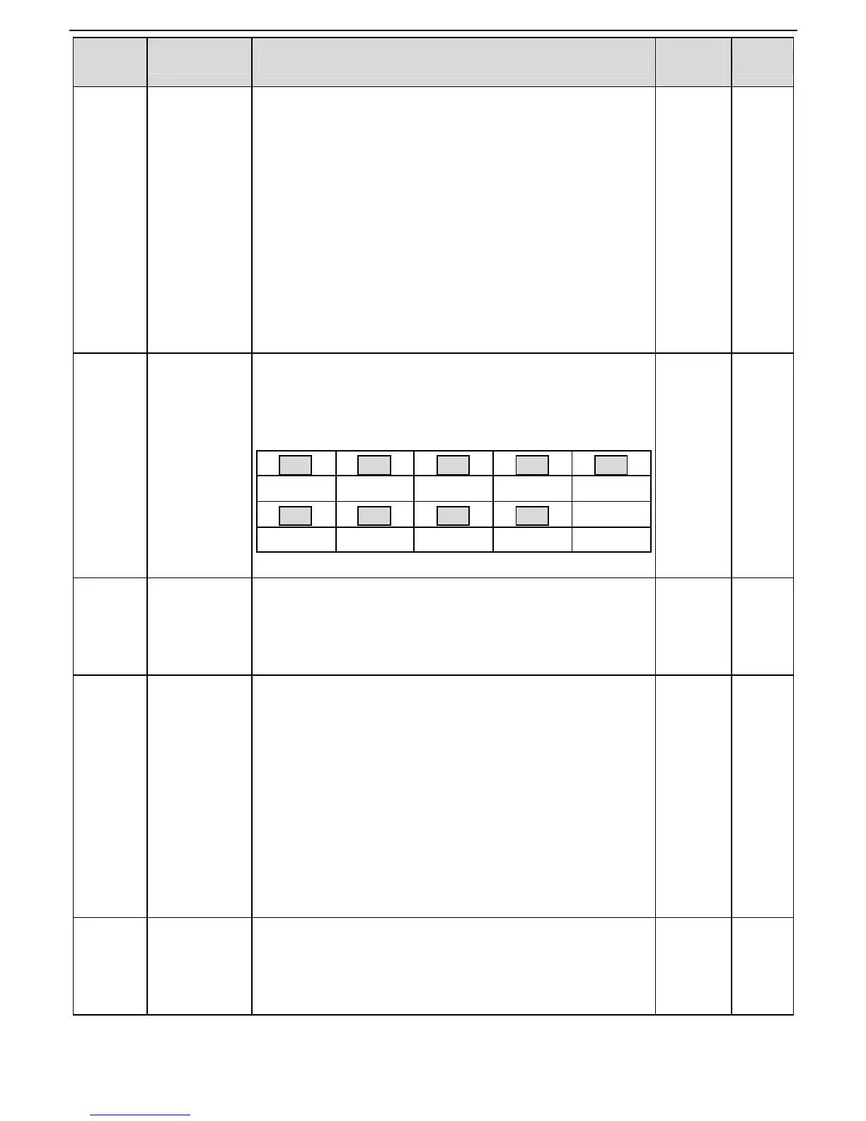
P05.10
The function code is used to set the polarity of the input
terminals.
Set the bit to 0, the input terminal is anode.
Set the bit to 1, the input terminal is cathode.
BIT8 BIT7 BIT6 BIT5 BIT4
HDI S8 S7 S6 S5
BIT3 BIT2 BIT1 BIT0
S4 S3 S2 S1
The setting range:0x000~0x1FF
0x000 ○
Switch filter
time
Set the sample filter time of S1~S4 and HDI terminals. If the
interference is strong, increase the parameter to avoid
wrong operation.
0.000~1.000s
0.010s ○
Virtual
terminals
setting
0x000~0x1FF(0: Disabled, 1:Enabled )
BIT0:S1 virtual terminal
BIT1:S2 virtual terminal
BIT2:S3 virtual terminal
BIT3:S4 virtual terminal
BIT4:S5 virtual terminal
BIT5:S6 virtual terminal
BIT6:S7 virtual terminal
BIT7:S8 virtual terminal
BIT8:HDI virtual terminal
0x000 ◎
mode
Set the operation mode of the terminals control
0:2-wire control 1, comply the enable with the direction. This
mode is widely used. It determines the rotation direction by
the defined FWD and REV terminals command.
0 ◎
 Loading...