Goodrive20-EU series VFD Installation guide
23
3.3 Overview of STO function
Reference standards: IEC 61508-1, IEC 61508-2, IEC 61508-3, IEC 61508-4, IEC 62061, ISO
13849-1, IEC 61800-5-2.
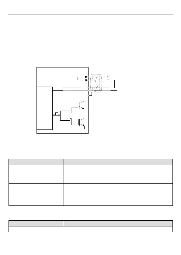
The STO function can be used where main power of the drive is on to prevent unexpected
start. The function cuts off the drive signal to disable the drive output, thus preventing motor
from unexpected start (refer to below figure). After enabling STO function, short-time
operations (like non-electrical cleaning-up in lathe industry) and/or maintenance on
non-electrical parts can be conducted.
Control
circuit
+24V
Switch, relay, etc.
UDC+
UDC-
Drive
circuit
PWM+
PWM-
U/V/W
H1
H2
Note: The contact of safety switch must be
opened/closed within 250ms; the cable between the
VFD and safety switch should be no longer than
25m.
COM
Figure 3-15 STO function schematic
3.3.1 Logic table for STO function
Input states and corresponding faults of STO function:
H1, H2 opens simultaneously
Trigger STO function, the drive can't operate normally
H1, H2 closes simultaneously
Don't trigger STO function, the drive can operate normally
Either H1 or H2 opens or
closes
Trigger STL1/STL2/STL3 fault, fault code:
38: Safety circuit of channel 1 is abnormal (STL1)
39: Safety circuit of channel 2 is abnormal (STL2)
40: Internal circuit is abnormal (STL3)
3.3.2 Description of STO channel delay
STO channel trigger and indication delay time:
STO trigger and indication delay
1), 2)
Trigger delay<10ms, Indication delay<280ms
 Loading...