Goodrive20-EU series VFD Function parameters
65
Detailed instruction of parameters
21: Reserved
22: Running time arrival
23: MODBUS communication virtual terminals
output
24 – 25: Reserved
26: Establishment of DC bus voltage
27: STO action
28 – 30: Reserved
Polarity
selection of
output
terminals
The function code is used to set the pole of the
output terminal.
When the current bit is set to 0, input terminal is
positive.
When the current bit is set to 1, input terminal is
negative.
Setting range: 0.000 – 50.000s
Setting range: 0.000 – 50.000s
RO1 switching
on delay time
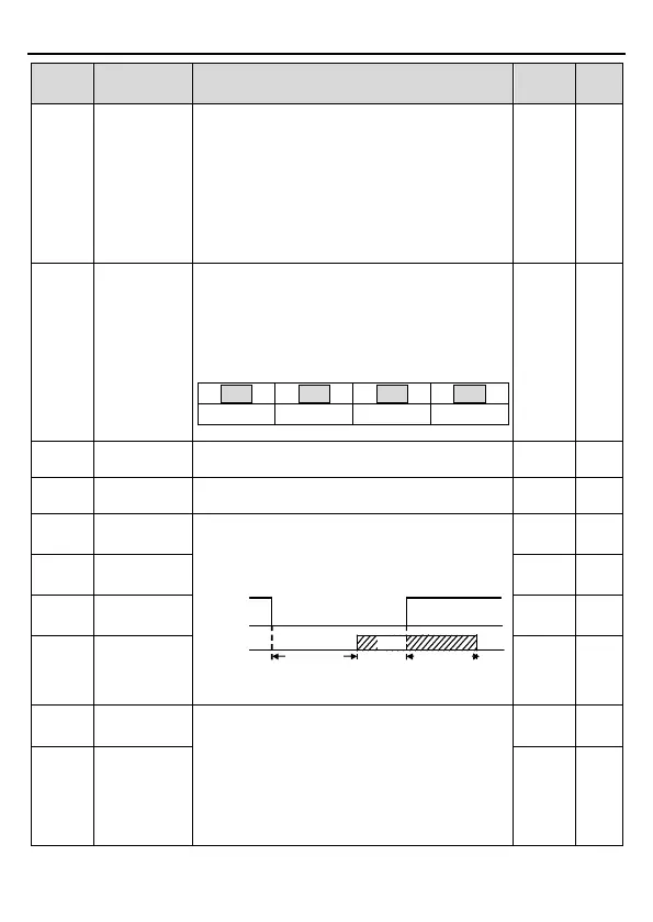
The function code defines the corresponding
delay time of the electrical level change during
the programmable terminal switching on and off.
RO electric level
RO valid Invalid
Switch on
delay
invalid
Valid
Switch off
delay
Setting range: 0.000 – 50.000s
RO1 switching
off delay time
RO2 switching
on delay time
RO2 switching
off delay time
0: Running frequency
1: Set frequency
2: Ramp reference frequency
3: Running speed (relative to twice the motor
synchronous rotational speed)
4: Output current (relative to twice the rated VFD
current)
 Loading...