GD200A series VFD Product overview
-12-
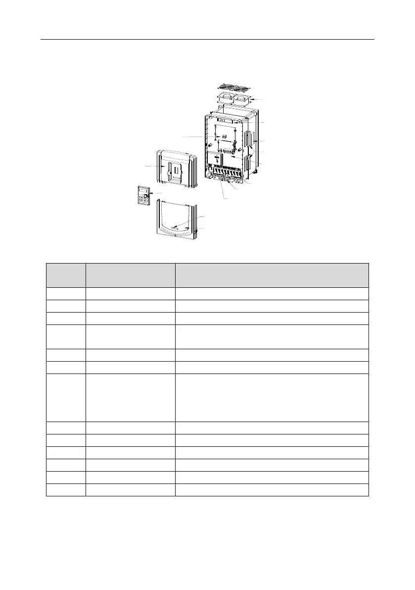
3.7 Structure diagram
Below is the VFD layout figure (taking the 030G/037P model for example).
Figure 3-5 Product structure diagram
Protect the internal parts and components
See 5.4 Keypad operationfor detailed information
See 8.8 Maintenance and hardware diagnostics for
detailed information
Connect to the control board and the drive board
See 3 Product overview for detailed information
Optional part. The side cover will increase the protective
degree of the VFD. The internal temperature of the VFD
will increase, too, so it is necessary to derate the VFD at
the same time
See 4 Installation guidelinesfor detailed information
See 4 Installation guidelines for detailed information
Fix the main circuit cable
See 3 Product overview for detailed information
Protect the internal parts and components
 Loading...