Goodrive300-01A series VFD for air compressor Appendix C
-82-
Appendix C Current transformer of the fan
C.1 Current transformer model selections
Power of the cooling
fan (kW)
Rated current A of
cooling fan
Recommended transformation
ratio of the transformer
Note:
1. The fan can sustain tripled overload at a short-time. In order to ensure the fan can be protected
by the VFD properly, the current on input side of the current transformer should be more than
three times of the rated current of the fan.
2. The transformation ratio of the current transformer must be 1000.
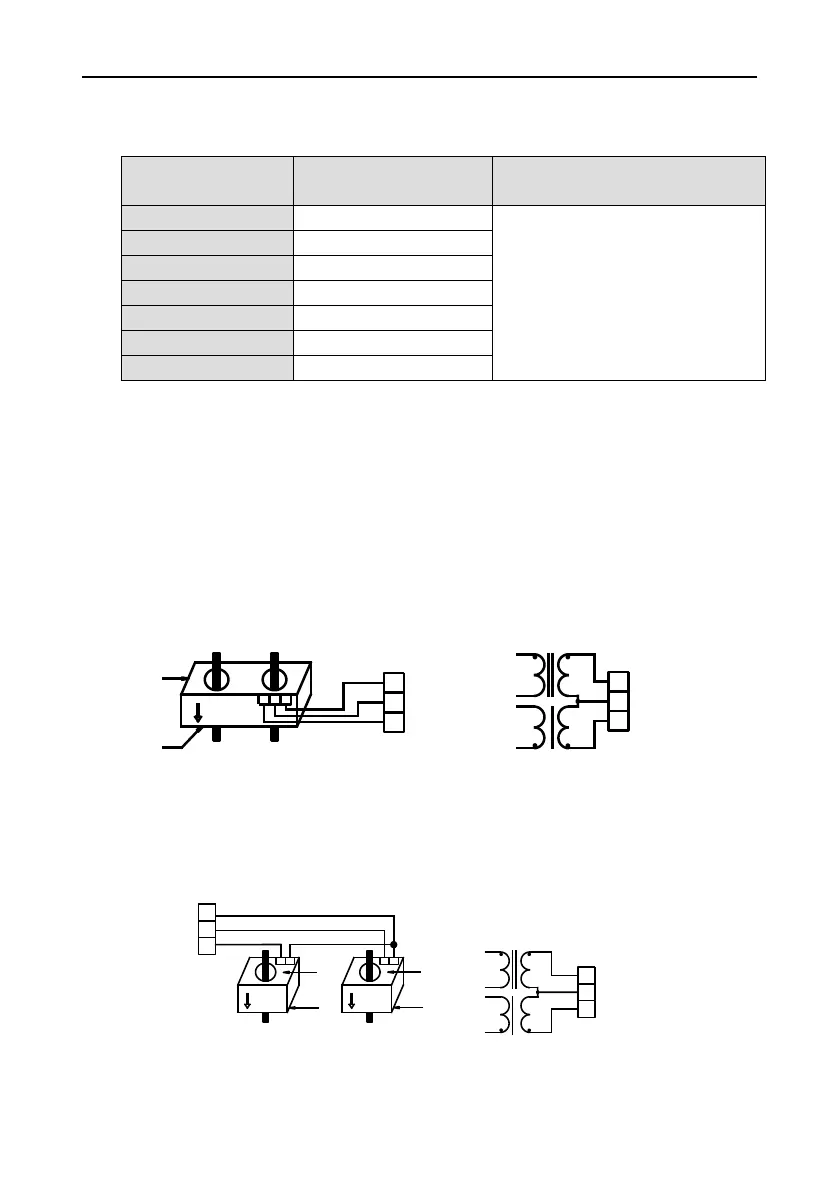
C.2 Wiring of current transformer of the fan
The transformer should be purchased by the user. The figure below illustrates the wiring precautions
for transformer. If the transformer actually used differs from the one shown in the figure below, please
consult with the transformer manufacturers.
1. If users adopt 2-phase combined current transformer, please refer to the wiring diagram below.
S/B phase R/A phase
c b a
Ic
Ia
Ib
to GD300-01A control
board
P1
P2
P2
P1
a
Dotted terminal of current transformer
P1
P2
b
c
Cables on the fan side
R/A phase
S/B phase
Ib
Ia
Ic
The main circuit cable must go in from P1 and out from P2. The coil a, b and c on output side of the
transformer must be connected to la, lb and lc respectively. A and B must correspond to a and b
respectively.
3. If users chose single current transformer, refer to the wiring diagram below.
R/A phase
current transformer
S/B phase
current transformer
to GD300-01A control board
Ia
Ib
Ic
P1
S1 S2 S1 S2
P2
P1
P2
Dotted terminal of current transformer
Cables on fan side
Cables on fan side
S/B相
R/A相
P2
P1
S1
P1
P2
S1
S2
Ib
Ic
Ia

 Loading...


