Goodrive300-01A series VFD for air compressor Wiring instruction
-14-
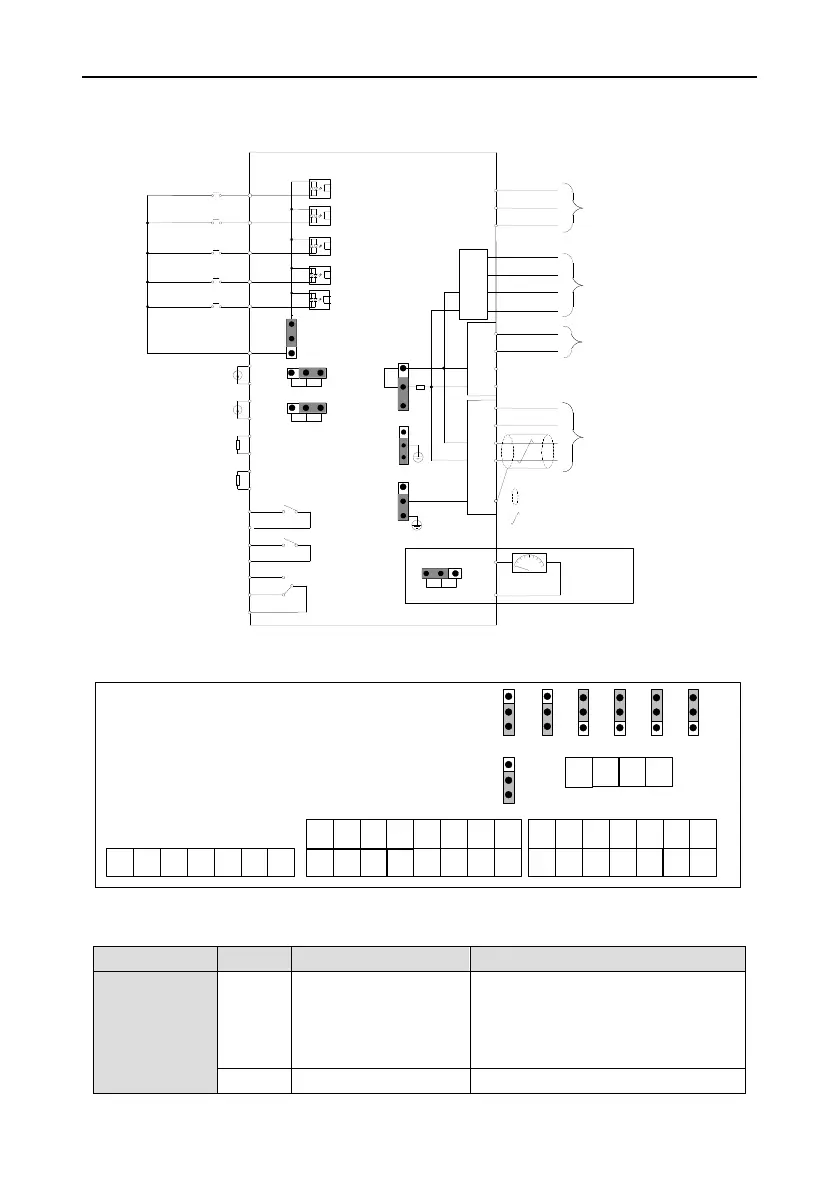
3.2 Control circuit wiring and terminal description
3.2.1 Control circuit wiring diagram
Emergency-stop
Fan fault
User-defined
User-defined
COM
S4
S3
S2
S1
S5
PTB1
PTA1
PTB2
PTA2
P1-
P1+
P2-
P2+
Ib
Ia
Ic
GND
+24V
485-
485+
PT100
PT100
Pressure transmitter
Pressure transmitter
V I
V I
J7
J8
CN10
ON
0-10V/0-20mA
Analog output
AO1
GND
V I
COM
PW
+24V
J9
J5
J2
J6
to current transformer
to power detection module
RO1C
RO1A
RO3C
RO3B
RO3A
Relay 1 output
Relay 3 output
RO2C
RO2A
Relay 2 output
GND
PE
GD300-01A series
--shielded cable
--twisted pair
to wireless data collection
terminal
to touch screen or
controller
GND
+24V
485-
485+
485+
GND
+24V
485-
CGND
/PE
CGND
J10
PE
CN7-10
User-defined
Figure 3-15 Control circuit wiring diagram
J7
J8 J2 J5
J6
J9
CN4
CN7
RO1A
RO1C
RO2A
RO2C
RO3ARO3BRO3C
CN8
CN10
CN7-10
+24V
PW
COM
J10
P1+ P1-
P2+
P2- PTA1
PTB1 PTA2 PTB2
COM
S1 S2 S3 S4 S5 COM COM
+24V
GND 485+ 485- Ia
Ib Ic
+24V
GND 485+ 485-
AO1GND
PE/C
GND
+24V
GND 485+ 485-
V
I
V
I
V
I ON
PE
GND
PE
CGND
Figure 3-16 Control circuit terminal diagram
Table 3-4 User terminal description of control circuit
Provide +24V±5% power to the external,
max. output current: 1A
Can be used to power up GPRS, touch
screen and power detection module
+24V, AO, Ia, Ib, Ic reference ground

 Loading...


