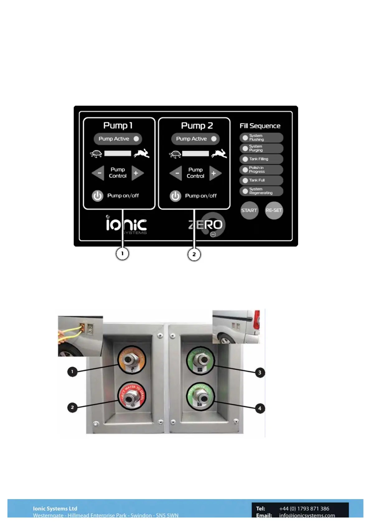
Delivery Pump Operation
The Control Panel (See Diagram on page 8) also houses the Delivery Pump Controllers.
They allow control of the volume of water to the water fed poles as well as switching on and
off. The left Pump (1) is the hot pump on a Thermopure™ system and the right pump (2) is
always a cold delivery pump. On a non-Thermopure™ system they are both cold.
1""
2
!
Pump No1 is connected to the upper port on the side of the vehicle (3) and No2 to the lower
(4). Prior to switching the pumps on connect up the water fed poles that are required for the
task and open the outflow shut-off valves between the system and the out ports in the
vehicle.
3