14
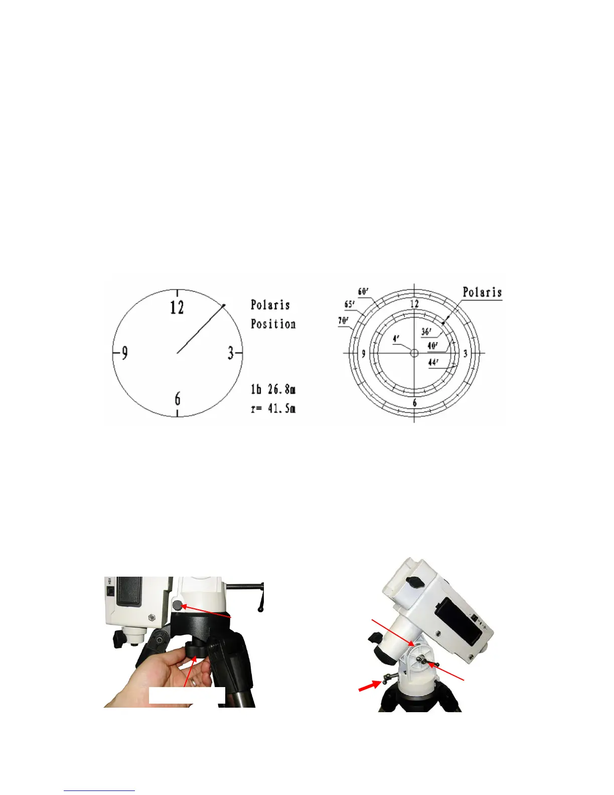
As indicated in Error! Reference source not found., the Polar Scope Dial has been divided into 12 hours
along the angular direction with half-hour tics. There are 2 groups, 6 concentric circles marked from 36’
to 44’ and 60’ to 70’, respectively. The 36’ to 44’ concentric circles are used for polar alignment in
northern hemisphere using Polaris. While the 60’ to 70’ circles are used for polar alignment in southern
hemisphere using Sigma Octantis.
5. Release R.A. Clutch Screw. Press the LFTT or RIGHT button on the hand controller to rotate the polar
scope to align the 12 o’clock position of the dial on the top, as shown in Error! Reference source not
found.. (Or align to the zero position mark on the R.A. unit as shown in Error! Reference source not
found.). You may press number 9 button to change the rotation speed to MAX.
6. Make sure that the time and site information of the hand controller is correct. Press the MENU button,
then select “Align” and “Pole Star Position” to display the current Polaris position. For example, on
May 30, 2010, 20:00:00 in Boston, United States (Lat N42º30’32” and Long W71º08’50”, 300 min behind
UT, DST set to Y), the Polaris Position is 1hr 26.8m and r = 41.5m, as shown in Figure 21 (a).
7. Adjust the mount in altitude (latitude) and azimuth (heading) direction to place Polaris in the same
position on the Polar Scope Dial as indicated on the HC LCD. In this case, the Polaris will be located at
a radius of 41.5’ and an angle of 1 hour 26.8 minute, as shown in Figure 21 (b).
(a) (b)
Figure 21. Place the Polaris at the position as shown on hand controller
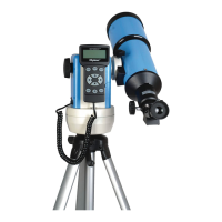
You need to loose Azimuth Lock a little and use Azimuth Adjustment Knobs to adjust the mount
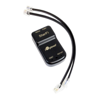
in azimuth (heading) direction (Figure 22). Unlock Latitude Clutch, and turn Latitude Adjustment Screw
or push the mount down to adjust the altitude (latitude), as shown in Figure 23. Secure all the locks
after the polar alignment is done.
Now the mount is polar aligned.
Figure 22. Azimuth adjustment
Figure 23. Latitude Adjustment
Azi. ad
. knob
X2
Azimuth lock
Latitude
Adj. Screw
Latitude
clutch
Latitude dial