7/39
B. Hardware Installation
i. Connect power adaptor
ii. Connect Ethernet cable to IP Camera
iii. Connect IP Camera to a computer or Local network.
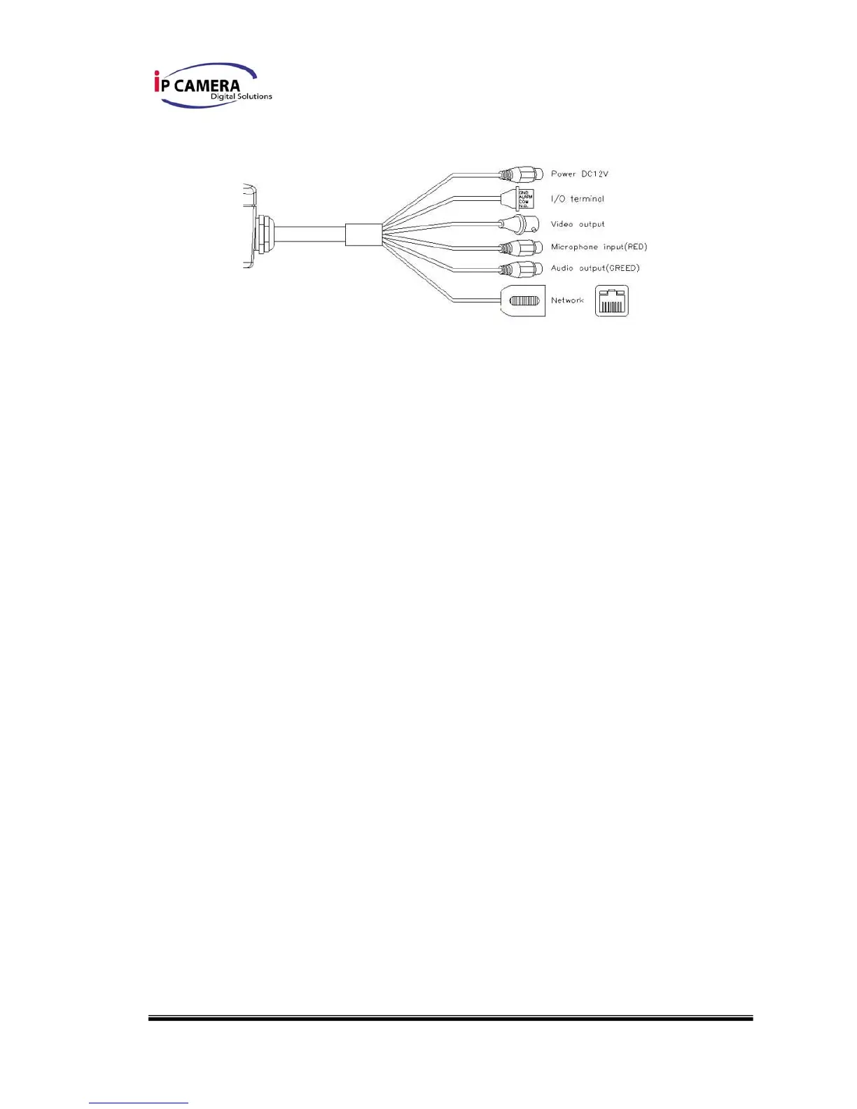
B-1 I/O Control Instruction
I/O terminal connector – used in application, for e.g., motion detection, event
triggering, alarm notifications. It provides the interface to:
1 Digital Input (GND+Alarm) – An alarm input for connecting devices that can toggle
between an open and closed circuit, for example: PIRs, door/window contacts, glass
break detectors, etc. When a signal is received the state changes and the input becomes
active.
1 Relay output (COM +N.O.) – An output to Relay switch, for example: LEDs, Sirens,
etc
Digital Input
Alarm Input
1. GND (Ground) : Initial state is LOW
2. Alarm : Max. 50mA, 12VDC
Relay Output
1. COM: (Common)
2. N.O. (Normally Open): Max. 1A, 24VDC or 0.5A, 125VAC