Page 09
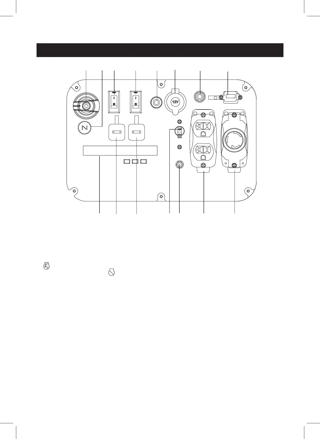
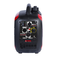
CONTROL PANEL FEATURES
NOTE: Total power drawn from all outlets must not exceed the nameplate rating.
1 2 3
4
5 6 7 8
12
1313
14
11
10 9
1. Fuel Valve Knob
2. Choke Knob: Pull the choke knob to adjust air intake.
3. Engine Control Switch: Flip the switch to the “ON (l)”
position and pull the recoil starter to start the
generator. Turn to the “OFF (O)” position to turn
off the generator.
4. Low Idle Switch: Low idle switch minimizes fuel
consumption and noise by adjusting the engine speed
to the minimum required for the current load.
5. Circuit Breaker(DC): Protects the generator against
electrical overloads.
6. 12V DC, Outlet (Automotive): Provides 12 volt DC
power up to 8.3 amps.
7. Circuit Breaker (AC): Protects the generator
against electrical overloads.
8. 5V DC, USB Outlet: Provides 5 volt DC power up to 1.5
amps.
9. 120V AC, 30A Twist Lock outlet, single phase,
60 Hz Outlet (NEMA L5-30R): This receptacle can
provide 120 volt output up to 30 amps.
10. 120V AC, 20A Duplex, Single Phase, 60 Hz Outlets
(NEMA 5-20R): Each outlet is capable of carrying a
maximum of 20 Amp on.
11. Ground Terminal: The ground terminal is used to
ground the generator.
12. Main Circuit Breaker: Protects the generator against
electrical overloads.
13. Parallel Operation Outlets: These outlets are used for
connecting two AIPOWER inverter generators for
parallel operation. Do not connect or disconnect
parallel cables while the generator is running to avoid
damage.
14. LED Multi-Meter: Displays voltage, frequency, fuel
remaining,power output,and total running time.