Iridium 9603 SBD Transceiver Product Developers Guide
Revision 3.1
Proprietary & Confidential Information
Distribution of guide restricted to product developers only • Information contained in this guide is subject to change without notice.
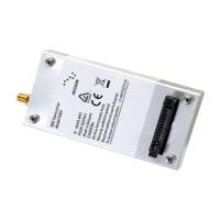
3.1.2 User Connector Pin Allocation
The user connector is surface mount, 0.4mm centerline terminal strip. Individual pin assignments are shown in Table 7 and the
limits for the digital signals are listed in Table 8. Multiple supply grounds are provided and all supply and supply grounds are
required to be connected to the power supply in order to limit the current on any one pin. Multiple signal grounds are provided to
reduce cross-talk.
Table 7: User Connector Pin Allocation
Signal direction
(WRT 9603/9603N)
Analog
On: >=2.0V
Off: <=0.5V
Data port, serial data input
Data port, serial data output
Data port, Data Carrier
Detect
Data port, Data Set Ready
Data port, Ring Indicator
Data port, Request-to-Send
Data port, Data Terminal
Ready
Signals when the
9603/9603N can see an
available satellite network
3.3V Digital
Available = high
Not available= low
Supply power indicator
output
* Note: This is the supply voltage range of the 9603; the 9603N has an extended supply voltage range of +5 V +/- 0.5 V
Table 8: Limits for 3.3V Digital Signals
High Level Output Current
 Loading...