Iridium 9603 SBD Transceiver Product Developers Guide
Revision 3.1
Proprietary & Confidential Information
Distribution of guide restricted to product developers only • Information contained in this guide is subject to change without notice.
4 RF Interface
This section describes the physical characteristics of the RF connectors and specifications of the RF Interface.
4.1 RF Connector
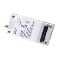
The 9603/9603N RF connector is a U.FL connector produced by Hirose. The part number is U.FL-R-SMT-1. This is a surface
mount connector that is directly attached to the 9603/9603N module. The U.FL connector mates with a pigtail which can link to an
antenna.
Note: The 9603/9603N module has a different antenna connector than other Iridium transceivers.
Note that for safety reasons, the RF connector on the 9603/9603N module should not be directly connected to an external antenna
cable or cable distribution system. Paragraph 7.3 of EN60950-1:2006 safety standard requires that users are protected against
high voltages that might appear on these cables. This can be achieved either by inserting a high-voltage isolating capacitor in
series with the signal or by grounding the shield of the coaxial cable. The 9602 RF connector has limited voltage capacity;
therefore, protection needs to be provided in the host application. Developers are encouraged to review the EN60950-1:2006
standard for additional details.
4.2 Antenna Implementation
4.2.1 Antenna Characteristics
The 9603/9603N should be connected to an Iridium-band antenna with the following antenna connector characteristics as
described in Table 11.
Table 11: Antenna Characteristics
4.2.2 Important Design Guidance for the 9603
The 9603* requires a load, i.e. antenna plus cable, to present a VSWR of less than 3:1 over the frequency range of 1.2 GHz to 2.0
GHz at the 9603 RF connector. This is the out-of-band VSWR requirement. In the event a particular antenna design does not meet
the out-of-band VSWR requirement, a combination of cable loss and passive attenuation, i.e. an attenuator, can be used to satisfy
the out-of-band VSWR requirement provided the total attenuation, cable plus attenuator, between the 9603’s RF connector and
antenna does not exceed 3 dB. A minimal amount of attenuation should be used to meet the out-of-band VSWR requirement for
best performance as well as a lower VSWR in the Iridium band.
*Note: The above design guidance applies only to the 9603 and not the 9603N
Note: Existing certified antennas will require different RF connector types than those for the 9601, 9602, 9522, 9522A and 9522B
 Loading...