Iridium 9603 SBD Transceiver Product Developers Guide
Revision 3.1
Proprietary & Confidential Information
Distribution of guide restricted to product developers only • Information contained in this guide is subject to change without notice.
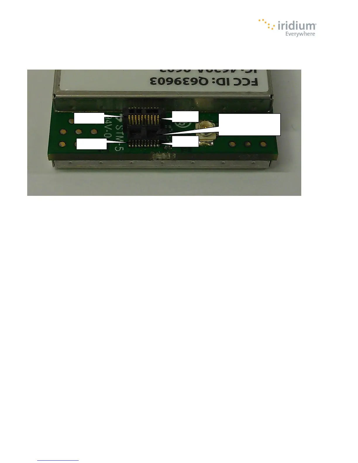
Figure 6 provides a reference for the pin designation. The pins are marked in the figure. Note that Pin 1 is marked on the
connector.
Figure 6. 9603/9603N User Connector Pin Number Designation
3.2 DC Power Interface
The DC power interface is comprised of the DC power inputs and a control signals as summarized in Table 7. The +5V Inputs and
0V supply returns are used to supply DC power to the 9603/9603N and ensure that enough current can be drawn across the
connector without the 9603/9603N malfunctioning during transmit due to lack of current supply. Note that all power and ground
pins should be connected externally.
The DC power supply requirements for the 9603/9603N are summarized in Table 9 below. Note that these requirements apply to
DC power measured at the 9603/9603N User connector input and not at the output of the power supply. Long power supply cables
can cause a voltage drop sufficient to cause the voltage to be out of specification at the physical power supply input to the
9603/9603N.
Pin 1 is marked on
the connector
 Loading...