14
2.10. NOTES FOR THE INSTALLER
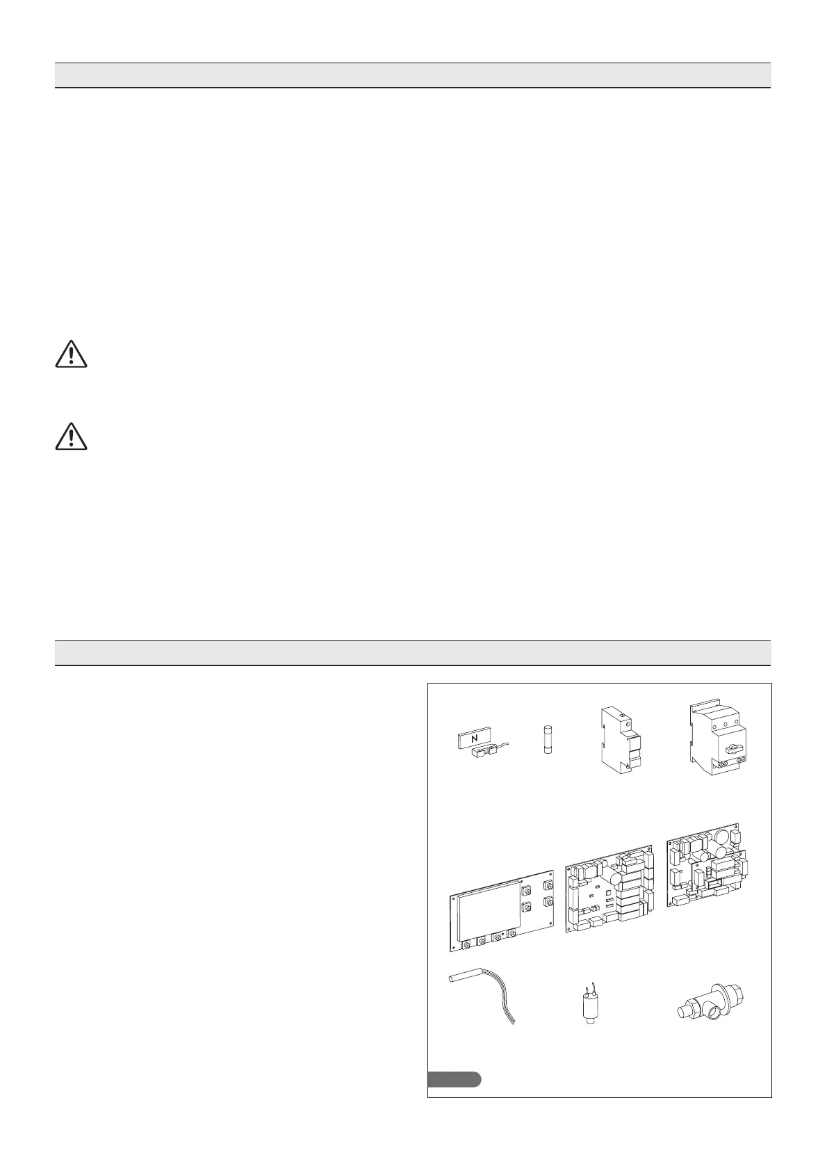
2.11. SAFETY AND CONTROL SYSTEMS
Fig. 19
•
•
•
•
•
•
•
•
•
•
•
•
•
•
•
Checking for correct installation and testing:
Check for possible gas leaks on welded parts or
joints made during installation.
Check for proper insulation of pipes connecting the
chiller with the remote condensing unit.
Check electrical connection.
Check power inputs.
Check the standard pressures.
Check water connection with the pressure valve
adjustment during operation as well as proper water
condensation circulation.
Run at least one complete conservation cycle (reach
the set temperature), and a manual defrost cycle.
Instruct the customer on the exact utilisation
of the chiller with specific reference to the use and
requirements of that specific customer.
Installation and commissioning must be
carried out by authorized personnel.
Door microswitch (A): blocks operation of the fans in
the cell when the door is opened
Protection fuses (B): protect the circuits against short
circuits and overloads.
Fuse holders (C): contain the fuses and allow
opening and disconnection of circuits.
Circuit breaker (D): protects the circuits against short
circuits and overloads.
Electronic cards (E): based on acquired parameters,
they control the various devices of the machine that
are connected to them.
Control of temperature in cell and end of defrosting
(F): managed by the electronic card via probe
PT1000.
Safety pressure switch (G): trips in the event of
excessive pressure in the refrigerant circuit.
Safety valve (H): trips in the event of excessive pres-
sure in the refrigerant circuit due to failure of the
safety pressure switch.
Fig.A Fig.B Fig.C Fig.D
Fig.E
Fig.HFig.GFig.F