-SENSOR-HD-00-SWITCH-(IO)-00-(R)(1) Installation Manual | Released
IRMA 6 components
Travel direction
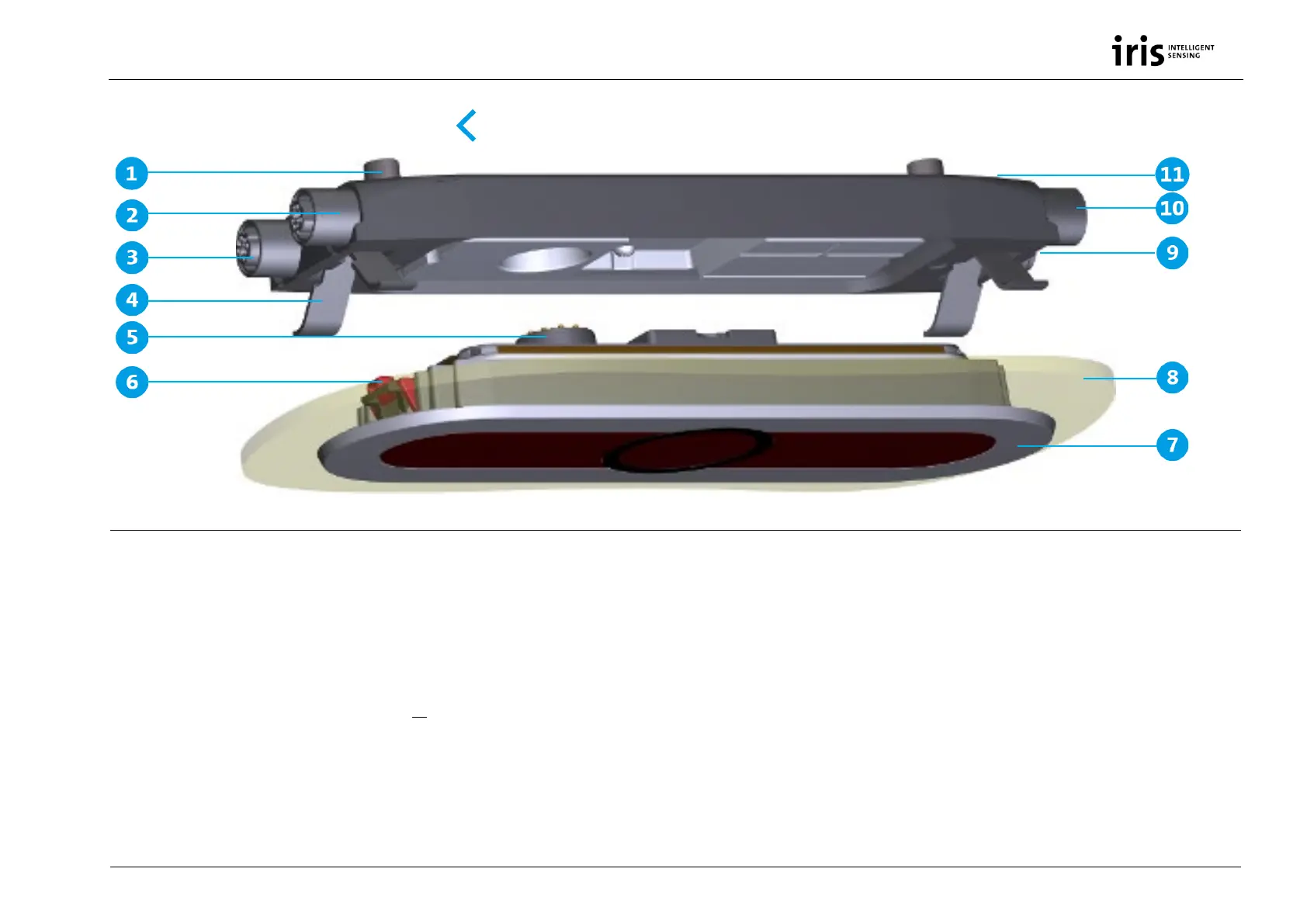
Fig. 2: IRMA 6 components
1 Mounting screws
2 M12 Ethernet connector (f)
3 M12 Ethernet connector
4 Leaf spring
5 Internal connector
6 Mounting hook
7 Sensor unit
8 Door panel
9 M12 power supply connector (m)
10 M12 door contact connector (on demand) (f)
11 Interface unit
IRMA 6 comes with normal M12 connectors or with angled M12 connectors to save space.