Page 14 of 16 IRIS Touch Quick Installation & Maintenance Guide Version 1.1
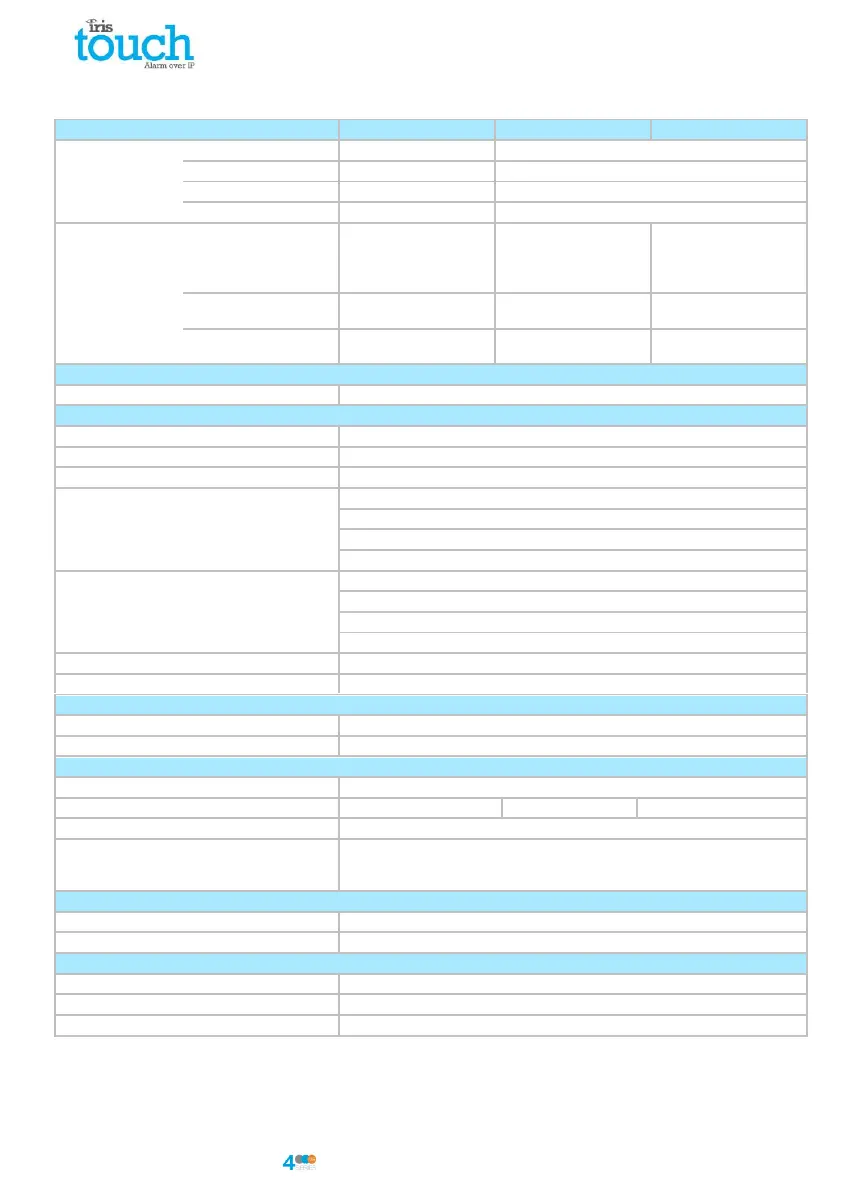
8. Specifications
UTP 10/100 Base T with auto-negotiation
RJ45 socket for CAT5 cabling
Connection fault detection
Loss of Ethernet synchronisation
(4G/CDMA optional
on request)
900/1800 MHz
Dual band UMTS
900/2100 MHz
900/1800 MHz
Dual band UMTS
900/2100 MHz
SMA socket for GPRS/3G
antenna connection
SMA socket for GPRS/3G
antenna connection
Connection fault detection
Loss of registration with
network
Loss of registration with
network
53165 (Alarms & Polling), 51292 (Diagnostic & Reflashing), 10001 (Upload/Download)
Interface to monitoring centre
IRIS Secure Apps or IRIS Management Suite via EN 50136-2 pass-through mode
Dial capture interface to alarm panel
Two wire interface via RJ45 socket or terminal block
Serial interface to alarm panel
RS485, TTL, RS232 x 2 Note: RS232 cabling must not exceed 30 meters
PIN Inputs interface to alarm panel
Maximum input voltage range 0V to +24V
Input ‘low’ (alarm) threshold < 1V
Input ‘high’ (restore) threshold > 2V
Internal pull-up impedance 10K to 3.3V supply
SIA (level 1 to 3) reference SIA DC-03-1990.01(R2003.10)
Contact ID reference SIA DC-05-1999.09
Robofon (Dial capture only)
Tamper detection reporting to monitoring centre
Dial capture interface, Serial interface, Pin inputs
Fault reporting to monitoring centre
Transmission interface/path fault
Maximum operating voltage
Note: For Radio & Telecoms Terminal Equipment Directive the power cable needs to be
no longer than 3 meters in length
Operating temperature range