Do you have a question about the ISA CBA1000 and is the answer not in the manual?
Details EMC directive and standards for emission and immunity.
Details Low Voltage Directive requirements and applicable standards.
Describes electronic driver characteristics, operating time accuracy, and current ranges.
Details main contact inputs, resistance ranges, test voltage, and current.
Explains auxiliary input types, test voltage, current, and connection.
Specifies sample rates, resolution, and timing accuracy for inputs.
Covers high and low voltage analog inputs, their specifications, and connections.
Details input voltage ranges, resolution, accuracy, impedance, and sampling rate.
Details input voltage range, resolution, accuracy, impedance, and sampling rate.
Covers trigger options for time measurement, including coil current and analog inputs.
Explains programmable sequences like Open, Close, OC, CO, OCO, and timing parameters.
Details static resistance measurement, test current, ranges, resolution, and accuracy.
Describes dynamic resistance measurement, recording contact resistance during close.
Covers local control via keypad, display, and interfaces like USB/RS232.
Details TDMS software features for test sequences, results viewing, editing, and saving.
Explains menu operation using the control knob and lists menu selection categories.
Lists mains supply, battery operation, housing, and included items.
Describes the option for static and dynamic resistance measurement and its code.
Details the option for four coil commands and its associated code.
Explains the internal thermal printer option and its code.
Describes the external thermal printer option and its code.
Covers options for Minimum Trip Coil test with different voltage modules.
Lists possible CBA1000 configurations and their corresponding option codes.
Details the basic set of connection cables included with the instrument.
Describes the set of long connection cables as an alternative option.
Details the transit case option for safe transportation and its specifications.
Explains the soft protection bag option for dust and scratch protection.
Describes the BSG1000 module for enhanced safety and specific test capabilities.
Lists optional linear and rotating transducers with their strokes and codes.
Details the Hall effect clip-on transformer for measuring DC current.
| Brand | ISA |
|---|---|
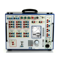
| Model | CBA1000 |
| Category | Measuring Instruments |
| Language | English |